Page 28
D-GAS HEAT COMPONENTS
See SPECIFICATIONS tables or unit nameplate for Btuh
capacities. Units are equipped with two identical gas heat
sections (gas heat section one and gas heat section two)
-
ken, hand tighten then turn additional 1/4” with a wrench
for metal to metal seal (do not overtighten).
NOTE - Do not use thread sealing compound on ex pipe
are connections.
1-Control Box Components A3, A12, A55
WARNING
Shock hazard. Disconnect power before
repairable. If control is inoperable, simply
replace entire control. Can cause injury
or death. Unsafe operation will resul if
repair is attempted.
Burner Ignition Control A3, A12
The ignition controls are located in the heat section areas
-
The ignition control provides three main functions: gas
attempt sequence provides three trials for ignition before
locking out. The lockout time for the control is 5 minutes.
After lockout, the ignition control automatically resets
and provides three more attempts at ignition. Manual re-
set after lockout requires breaking and remaking power
TABLE 6
UTEC
LED
Flashes
Indicates
Slow Flash Control ok, no call for heat
Fast Flash Control ok, call for heat present.
Internal control fault or no power
Steady On
Failure
Control internal failure
1 Flash Rollout switch open
2 Flashes Limit open or lockout from to many tries
during a single heat demand
3 Flashes Pressure switch open with inducer on/
4 Flashes
5 Flashes Flame sensed out of sequence
7Flashes Gas valve relay failure
8 Flashes Lockout due to too many pressure switch
openings during one heat demand
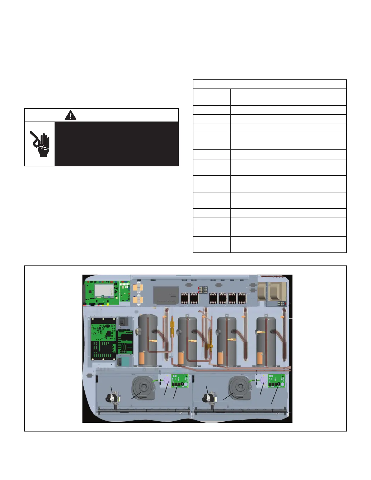
A12
A3
3VG1VG
S18
S45
B6
B15
Heat Section 1
Heat Section 2
FIGURE 14

 Loading...

