Page 50
X-VAV System
Units contain a supply air blower equipped with a variable
A-Start-Up
1 - A pressure transducer (A30) is shipped in a box
in the blower compartment. Install the transducer
according to manufacturer’s instructions.
Note - Make sure the transducer is installed in the
main duct at least 2/3 of the distance away from the
unit.
2 - Two twisted pairs of shielded cable must be used to
P378 connector is hanging in the control box.
3 - Open all zone dampers and/or boxes.
4 -
5 - Use the mobile service app to calibrate the blower
CFM. Select this menu to start the blower:
SETUP > TEST & BALANCE > BLOWER
The mobile app will display the percent of blower speed.
Press NEXT and follow the instructions to calibrate
static pressure. If the static pressure meets the
setpoint. If the static pressure does not meet the
NEXT to set the setpoint.
7 -
8 - If the desired CFM cannot be met with current
pulley setup, refer to the Blower Operation and
Adjustments section to adjust CFM.
TABLE 26
RECORD ADJUSTED SETPOINTS
Parameter
Setpoint
Description
Setpoint
“w.c.
Display
Setting
Smoke
387 Ventilation
388 Heating
Cooling
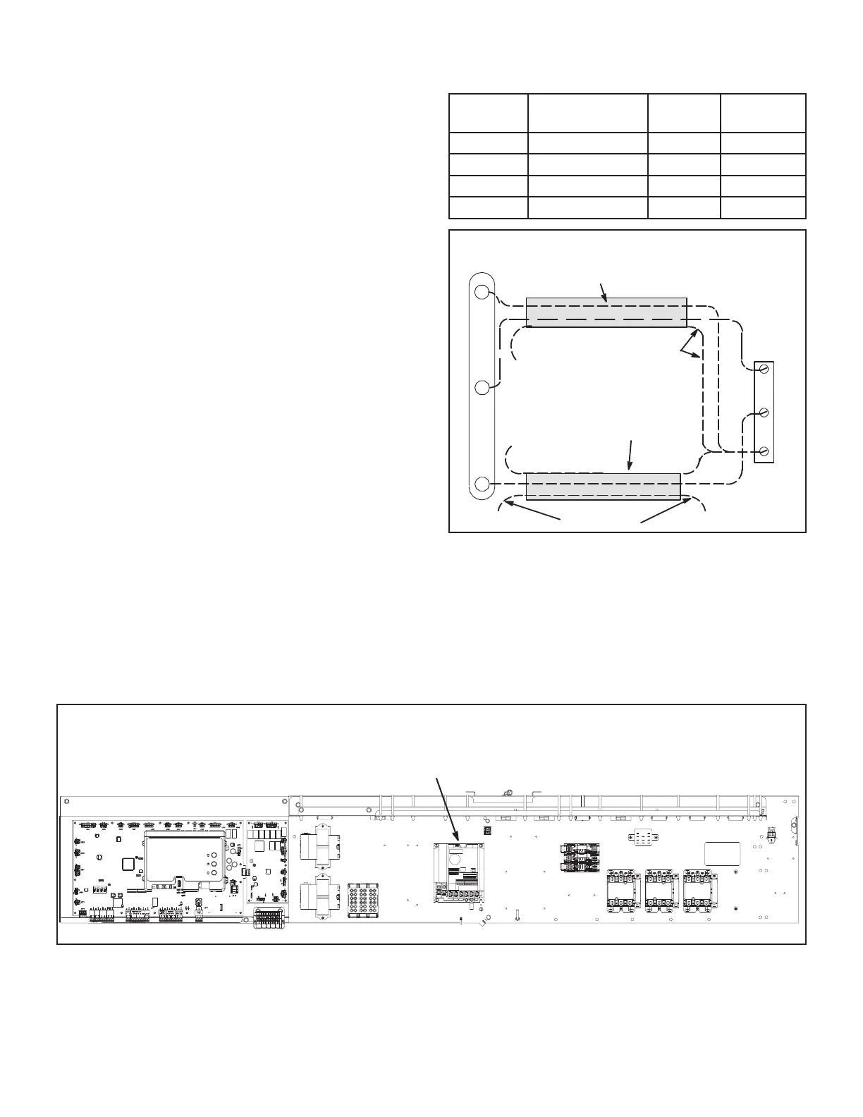
PRESSURE TRANSDUCER WIRING
TWISTED
PAIR
UNUSED WIRE
DRAIN
NOT
CONNECTED
NOT
CONNECTED
TWISTED
PAIR
A30
+S
_
+
P378
1
2
3
FIGURE 36
Note - The Unit Controller will lock-out the unit for 5 min-
utes if static pressure exceeds 2.0”w.c. for 20 seconds.
The Unit Controller will permanently shut down the unit af-
ter three occurrences. See mobile service app parameters
110, 42, and 43 to adjust default values.
CONTROL AREA
A96
SUPPLY AIR VFD
Figure 37

 Loading...

