Page 33
10-Spark Electrodes
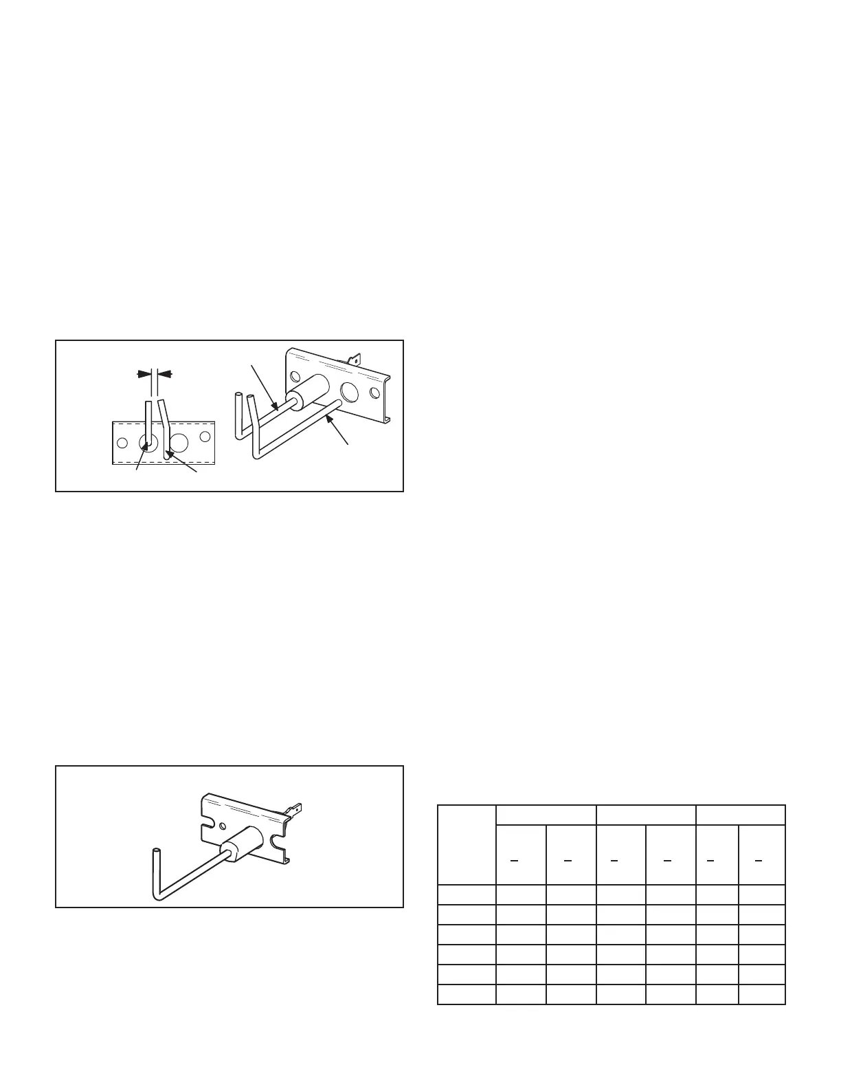
An electrode assembly is used for ignition spark. Two iden-
tical electrodes are used (one for each gas heat section).
The electrode is mounted through holes on the left-most
end of the burner support. The electrode tip protrudes into
assembly is fastened to burner supports and can be re-
moved for service without removing any part of the burn-
ers. During ignition, spark travels through the spark elec-
from burner to burner until all are lit. The spark electrode is
connected to the ignition control by a 8 mm silicone-insu-
mm)female quick connect on the electrode end and fe-
male spark plug-type terminal on the ignition control end.
NOTE- IN ORDER TO MAXIMIZE SPARK ENERGY TO
ELECTRODE, HIGH VOLTAGE WIRE SHOULD TOUCH
UNIT CABINET AS LITTLE AS POSSIBLE.
GROUND
ELECTRODE
GROUND
ELECTRODE
(3.2 mm ± .4 mm)
FIGURE 23
11-Flame Sensors
-
er support. The sensor is mounted through a hole in the
-
lope of the right most burner. The sensor assembly is fas-
tened to burner supports and can be removed for service
without removing any part of the burners.
-
passed along the ground electrode (located on the spark
-
trode. The ignition control allows the gas valve to stay
FIGURE 24
II-PLACEMENT AND INSTALLATION
Make sure the unit is installed in accordance with the in-
stallation instructions and all applicable codes. See ac-
cessories section for conditions requiring use of the op-
tional roof mounting frame.
III-CHARGING
A-Refrigerant Charge and Check - Fin/Tube Coil
NOTE- Do not exceed nameplate charge under any con-
dition.
This unit is factory charged and should require no further
adjustment. If the system requires additional refrigerant,
reclaim the charge, evacuate the system and add required
nameplate charge.
NOTE - System charging is not recommended below 60°F
(15°C). In temperatures below 60°F (15°C), the charge
must be weighed into the system. If weighing facilities are
not available, or to check the charge, use the following
procedure:
IMPORTANT - Charge unit in normal cooling mode.
1 - Attach gauge manifolds to discharge and suction
lines. With the economizer disabled, operate
the unit in cooling mode at high speed using the
following mobile service app (the QR code is in the
unit control area) menu path:
SERVICE>TEST>COOL>COOL 4
2 - Use a thermometer to accurately measure the
outdoor ambient temperature.
3 -
18 to determine normal operating pressures.
Pressures are listed for sea level applications at
4 - Compare the normal operating pressures to
the pressures obtained from the gauges. Minor
variations in these pressures may be expected due
could mean that the system is not properly charged
or that a problem exists with some component in
the system. Correct any system problems before
proceeding.
5 - If discharge pressure is high, remove refrigerant
from the system. If discharge pressure is low, add
refrigerant to the system.
• Add or remove charge in increments.
• Allow the system to stabilize each time refrigerant is
added or removed.
Use the following approach method along with the
TABLE 9
Outdoor
Coil
Entering
Air
Temp
Circuit 1 Circuit 2 Circuit 3
Dis.
+10
psig
Suc.
+5
psig
Dis.
+10
psig
Suc.
+5
psig
Dis.
+10
psig
Suc.
+5
psig
228 127 131 258 140
130 134 148
133 337 340 153
352 135 383 387
403 432 142 433
457 142 485 145

 Loading...

