Page 31
sensing electrode, gas valve and combustion air blower.
valve are directly controlled by ignition control. Ignition
control and combustion air blower is controlled by Unit
Controller A55.
Burners
Burners are factory set and do not require adjustment.
A peep hole with cover is furnished in the heating ac-
with the access panel in place.
Burners can be removed individually for service. Burn-
er maintenance and service is detailed in the SERVICE
CHECKS section of this manual.
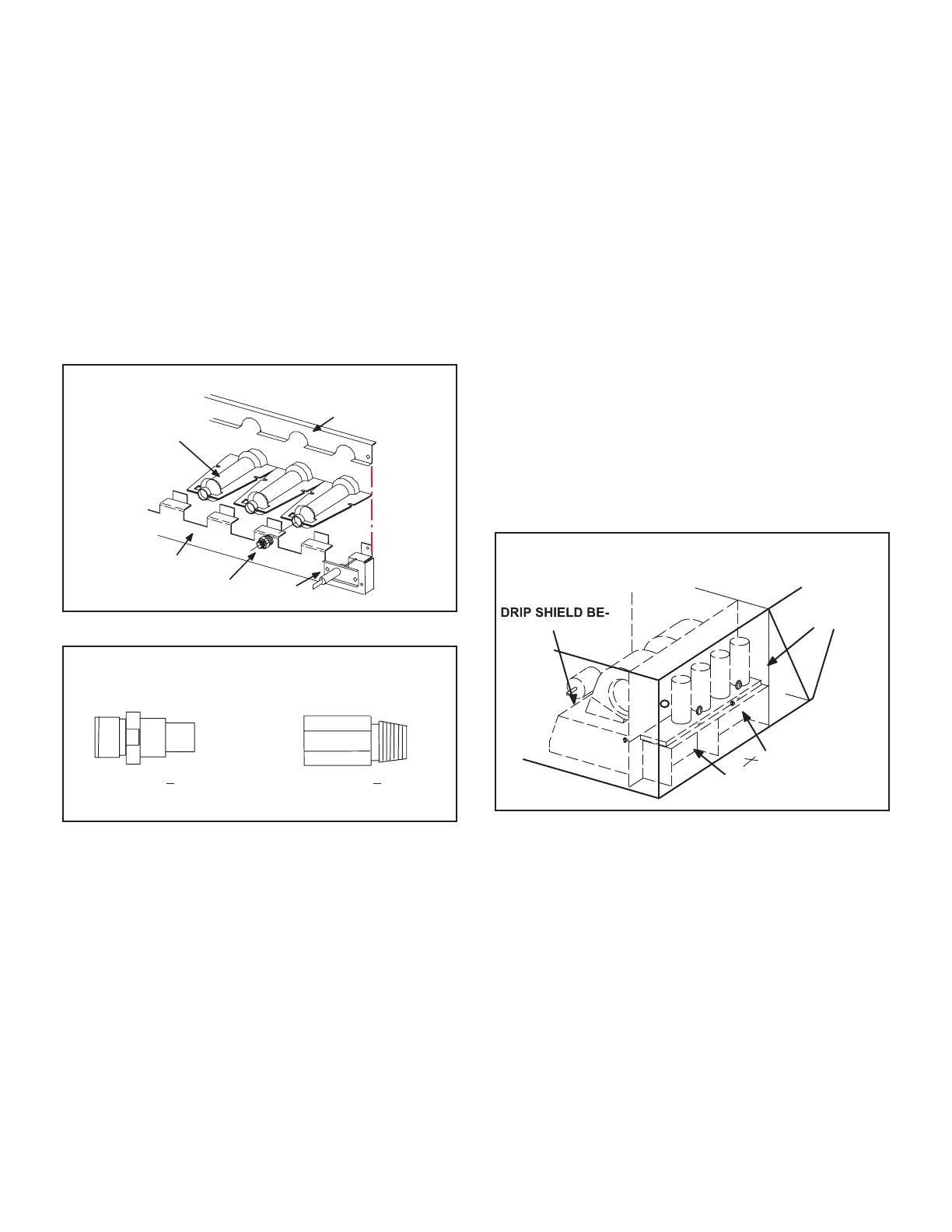
TYPICAL GAS BURNER ASSEMBLY
BURNERS
ORIFICE
SENSOR
BURNER
SUPPORT
BURNER
SUPPORT CAP
FIGURE 19
ORIFICE WITH
PIPE THREADS
Tighten to 6.25 + .5 ft.lbs.
Do not over-tighten.
Tighten to 14 + .5 ft/lbs
Do not over-tighten.
ORIFICE WITH
STRAIGHT THREADS
FIGURE 20
Orice
is precisely matched to the burner input. Install only the
into the burner manifold. The burner is supported by
NOTE-Do not use thread sealing compound on the or-
ices. Using thread sealing compound may plug the
orices.
unit. Refer to Repair Parts Listing for correct sizing in-
formation.
NOTE- In primary and secondary high temperature limits
S10 and S99 the ignition circuits in both gas heat sections
one and two are immediately de-energized when termi-
nals 1-3 open and the indoor blower motor is immediately
energized when terminals 1-2 close. This is the primary
and secondary safety shut-down function of the unit.
4-Primary High Temperature Limits S10 & S99
S10 is the primary high temperature limit for gas heat sec-
gas heat section two.
shield behind the blower housing. In this location S10 and
Primary limit S10 is wired to the Unit Controller A55 which
wired to the A55 Unit Controller which energizes burner 2
control (A12). Its N.C. contacts open to de-energize the
ignition control when excessive temperature is reached in
the blower compartment. At the same time, the N.O. con-
K3 through control A55. If either limit trips the blower will
be energized. Limits settings are factory set and cannot
be adjusted. If limit must be replaced same type and set
point must be used. See Repair Parts Handbook.
S10 and S99 Location
CONDENSER
DIVIDER
PANEL
S10 AND S99 ON
HIND BLOWER
HOUSING
GAS HEAT
SECTION 1
GAS HEAT
SECTION 2
FIGURE 21
 Loading...


