Page 38
TABLE 20
Manifold Pressure “W.C.
Supply Pressure
“W.C.
Natural LP/Propane Natural Propane
Low High Low High
4.7-10.5 10.8-13.5
+ 0.2 3.7+0.3 5.5+ 0.3 10.5+ 0.5
Combustion gases
Flue products must be analyzed and compared to the unit
may make it necessary to temporarily shut down the fur-
nace until the items can be repaired or replaced.
5-Proper Gas Flow
input from unit rating plate or the gas heating capacity in
the SPECIFICATIONS tables. Divide this input rating by
the Btuh per cubic foot of available gas. Result is the num-
gas through gas meter for two minutes and multiply by 30
NOTE - To obtain accurate reading, shut o all other gas
appliances connected to meter.
6-Inshot Burner
Burners are factory set for maximum air and cannot be
adjusted. Always operate unit with access panel in place.
A peep hole is furnished in the heating access panel for
some clear streaks. L.P. gas should burn mostly blue with
some clear yellow streaks.
Figure 27 shows how to remove burner assembly.
1 -
2 - Remove screws holding the burner support cap.
3 -
4 - Clean and reassemble (reverse steps 1-3).
5 - Be sure to secure all wires and check plumbing.
Turn on power to unit. Follow lighting instructions
attached to unit and operate unit in heating mode.
yellow streaks.
7-Spark Electrode Gap
The spark electrode assembly can be removed for inspec-
tion by removing two screws securing the electrode as-
sembly and sliding it out of unit.
For proper unit operation, electrodes must be positioned
and gapped correctly.
Spark gap may be checked with appropriately sized twist
drills or feeler gauges. Disconnect power to the unit and
remove electrode assembly. The gap should be between
0.125” + 0.015” (3.2 mm +
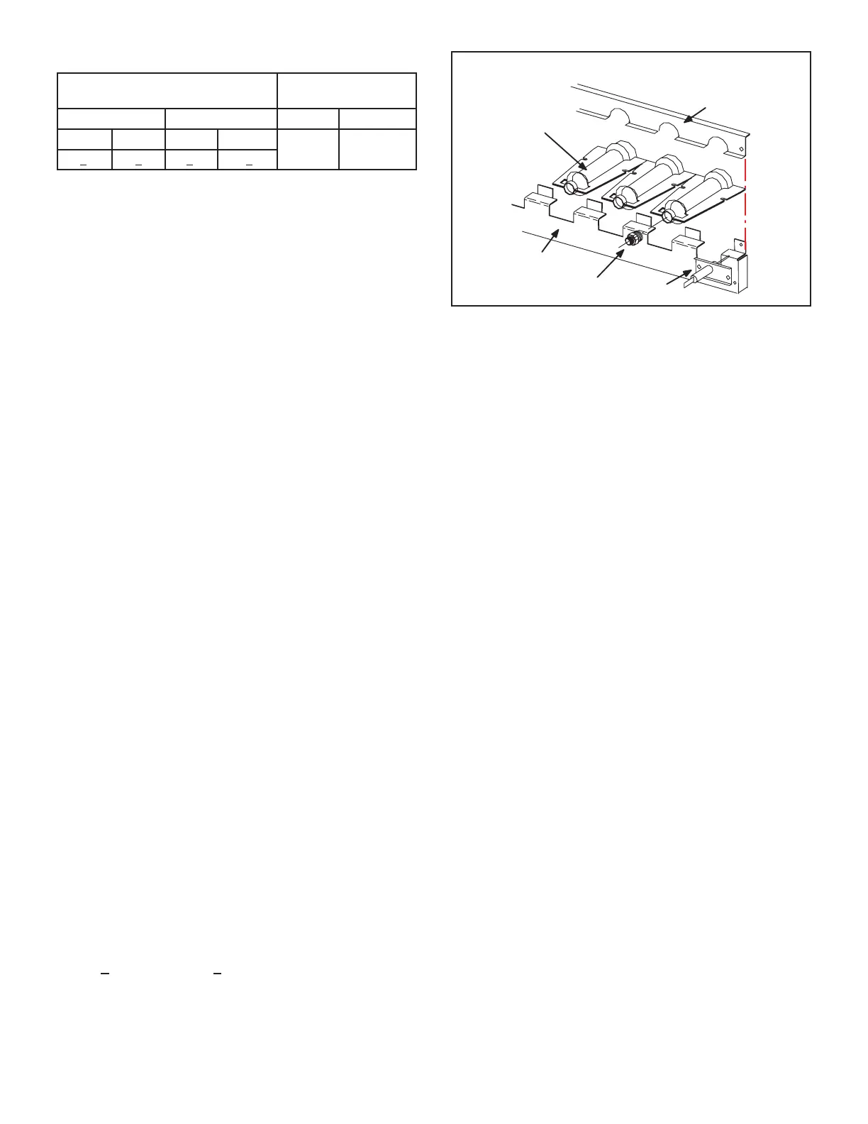
TYPICAL GAS BURNER ASSEMBLY
BURNERS
ORIFICE
SENSOR
BURNER
SUPPORT
BURNER
SUPPORT CAP
FIGURE 27
8-Heat Exchanger
To Access or Remove Heat Exchanger From Unit:
1 -
2 - Remove access panel(s) and unit center mullion.
3 - Remove gas valve, manifold assembly and burners.
4 -
careful attention to the order in which gaskets and
5 - Support heat exchanger (to prevent it from falling
Remove screws supporting heat exchanger.
7 - To install heat exchanger, reverse procedure. Be
sure to secure all wires and check plumbing and
burner plate for airtight seal. Screws must be
torqued to 35 in.-lbs. to ensure proper operation.
9-Flame Sensing
Flame current is an electrical current which pas es from
the ignition control through the sensor electrode during
unit operation.
complete a safety circuit. The electrodes should be locat-
-
rent, follow the procedure on the following page:
NOTE-Electrodes are not eld adjustable. Any alterations
to the electrode may create a hazardous condition that
can cause property or personal injury.
1 - Disconnect power to unit.
2 - Remove lead from sensing electrode and install
a 0-50DC microamp meter in series between the
sensing electrode and the sensing lead.
3 - Reconnect power and adjust thermostat for heating
demand.
4 -
table 21. Do not bend electrodes.
5 - Disconnect power to unit before disconnecting
meter.Make sure sensor wire is securely
reconnected before reconnecting power to unit.

 Loading...

