EasyManua.ls Logo

Lennox Merit CBA25UHE User Manual

Lennox Merit CBA25UHE
21 pages
To Next Page IconTo Next Page
Page #1 background imageLoading...
Page #1 background image
©2023 Lennox Industries Inc.
Dallas, Texas, USA
Page 1
THIS MANUAL MUST BE LEFT WITH THE
HOMEOWNER FOR FUTURE REFERENCE
WARNING
Improper installation, adjustment, alteration, service
or maintenance can cause property damage, personal
injury or loss of life. Installation and service must be
performed by a licensed professional HVAC installer or
equivalent, service agency, or the gas supplier.
IMPORTANT
The Clean Air Act of 1990 bans the intentional venting of
refrigerant (CFCs, HCFCs and HFCs) as of July 1, 1992.
Approved methods of recovery, recycling or reclaiming
must be followed. Fines and/or incarceration may be
levied for noncompliance.
WARNING
To prevent serious injury or death:
1. Lock-out/tag-out before performing maintenance.
2. If system power is required (e.g., smoke detector
maintenance), disable power to blower, remove fan
belt where applicable, and ensure all controllers
and thermostats are set to the “OFF” position before
performing maintenance.
3. Always keep hands, hair, clothing, jewelry, tools, etc.
away from moving parts.
INSTALLATION
INSTRUCTIONS
MULTI-POSITION AIR HANDLERS
508370-01
6/2023
Merit
®
Series
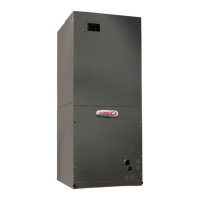
CBA25UHE Air Handler Units
Shipping and Packing List
Package 1 of 1 contains:
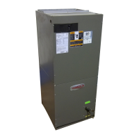
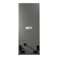
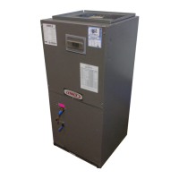
1 – Assembled air handler unit factory-equipped for upow
or horizontal air discharge application (includes upow
and horizontal drain pans and preinstalled air lter).
Check the air handler for shipping damage; if found, im-
mediately contact the last carrier. Check the unit rating
plate to conrm that delivered unit matches order.
IMPORTANT: Special procedures are required for clean-
ing the all-aluminum coil in this unit. See page 19 in this
instruction for information.
Table of Contents
Unit Dimensions – Upow Position.................................2
Unit Dimensions – Horizontal Position ..........................3
General Information .......................................................4
Requirements ................................................................4
Installation Clearances ..................................................5
Installation .....................................................................5
Condensate Drain...........................................................8
Duct System and Filters ...............................................9
Brazing Refrigerant Lines ............................................ 10
Sealing the Unit ...........................................................13
Electrical Connections ................................................. 13
Air Flow – Cooling Blower Speed ................................ 16
Blower Data ................................................................17
Check-out Procedures .................................................18
Operation ....................................................................18
Homeowner Maintenance ............................................19
Repairing or Replacing Cabinet Insulation ..................19
Professional Maintenance ...........................................19
Use of Air Handler During Construction .......................19
Question and Answer IconNeed help?

Do you have a question about the Lennox Merit CBA25UHE and is the answer not in the manual?

Lennox Merit CBA25UHE Specifications

General IconGeneral
ModelCBA25UHE
TypeAir Handler
RefrigerantR-410A
ConfigurationUpflow/Horizontal
Voltage208/230V
StagesSingle stage
SEER RatingUp to 16 SEER
DimensionsVaries by model
Nominal Cooling Capacity2.5 Tons
AirflowVaries by model
Motor TypeECM
HeightVaries by model
WidthVaries by model
DepthVaries by model
WeightVaries by model

Summary

Unit Dimensions and Specifications

Unit Dimensions – Upflow Position

Provides detailed dimensions and diagrams for the air handler in an upflow installation.

Unit Dimensions - Horizontal Position

Provides detailed dimensions and diagrams for the air handler in a horizontal installation.

Installation Overview and Requirements

General Information

Describes the air handler's design, intended use, and general installation guidance.

Requirements

Outlines critical requirements and codes for installation, including safety warnings.

Installation Clearances

Specifies required clearances for various installation scenarios, including closet installations.

Installation Procedures and Configurations

UPFLOW APPLICATION

Details specific steps for installing the unit in an upflow configuration, including drain pan modification.

HORIZONTAL APPLICATIONS

Provides important notes and recommendations for horizontal installations, including drain pan requirements.

RIGHT-HAND DISCHARGE

Instructions for configuring the unit for right-hand discharge, including drain plug modifications.

LEFT-HAND AIR DISCHARGE

Field modifications required for left-hand air discharge installation, including coil assembly handling.

DOWNFLOW APPLICATION

Notes on downflow applications, including the need for a separate kit and specific breaker rotation.

Condensate Drainage System

Condensate Drain

Detailed instructions and diagrams for installing main and overflow condensate drains, including trap requirements.

SLOPING THE UNIT

Guidance on properly sloping the unit to ensure complete condensate drainage.

INSTALL CONDENSATE DRAIN

Step-by-step instructions for connecting condensate drain lines and testing for leaks.

Ductwork and Filters

Duct System and Filters

Details duct system sizing, insulation, and filter specifications for the unit.

INSTALLING DUCT SYSTEM

Instructions for connecting the supply air duct and fabricating return air duct flanges.

Refrigerant Line Installation

Brazing Refrigerant Lines

Crucial safety warnings and procedures for brazing refrigerant lines.

Refrigerant Lines

Guidance on routing, insulating, and connecting refrigerant lines, including protection during brazing.

Brazing Connections

Detailed steps and diagrams for making refrigerant line connections using brazing and nitrogen purge.

Electrical System Setup

Sealing the Unit

Importance of sealing the unit to prevent moisture issues and ensure proper insulation.

Electrical Connections

Critical safety guidelines for electrical wiring, grounding, and circuit protection.

Control Panel Relocation

Instructions for relocating the control panel in specific configurations.

208 VOLT CONVERSION

Steps to convert the unit's power supply from 240V to 208V.

Typical Wiring Diagram – Electric Heat

Detailed wiring diagrams for electric heat configurations, including component identification and timing.

Blower and System Operation

Thermostat Designations

Explains thermostat wiring designations and their relation to indoor unit functions.

Air Flow – Cooling Blower Speed

Guidance on setting blower speed for optimal cooling performance.

Blower Data

Provides performance data tables for various blower speeds, static pressures, and CFM/Watts.

Check-out Procedures

A comprehensive checklist for pre-start-up checks, blower, cooling, and electric heat operation.

Operation

Describes the operational logic for cooling and heating modes.

Maintenance and Special Use Guidelines

Homeowner Maintenance

Routine maintenance for homeowners, focusing on air filters.

Repairing or Replacing Cabinet Insulation

Instructions for repairing or replacing damaged cabinet insulation.

Professional Maintenance

Guidelines for professional cleaning of the aluminum coil, including pH levels.

Use of Air Handler During Construction

Conditions for using the unit during construction to prevent damage.

Start-Up and Performance Verification

Start-up and Performance Checklist (Upflow Configuration)

A checklist for verifying system installation and performance during start-up in upflow mode.

Start-Up and Performance Checklist (Horizontal Configuration)

A checklist for verifying system installation and performance during start-up in horizontal mode.
Related product manuals