Page 20
Table 8. Merit
®
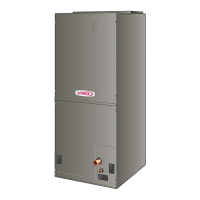
CBX25UHV‐048 Air Handler Performance (0 through 0.80 in. w.g. [0 — 200 Pa] External Static Pressure Range)
“ADJUST”
Jumper
Setting
Jumper Speed Positions
“HEAT” Speed First-Stage “COOL” Speed Second-Stage “COOL” Speed
1 2 3 4 1 2 3 4 1 2 3 4
cfm cfm cfm cfm cfm cfm cfm cfm cfm cfm cfm cfm
+ 1450 1670 1880 2340 1050 1200 1340 1650 1440 1670 1950 2340
NORM 1340 1520 1730 2100 950 1100 1230 1520 1325 1530 1740 2150
– 1210 1390 1570 1915 850 1000 1110 1375 1200 1380 1600 1950
NOTES
The effect of static pressure, filter and electric heater resistance is included in the air volumes listed.
First-stage cooling air volume is 70% of COOL (second-stage) speed setting. Continuous blower speed is approximately 50% of COOL speed setting.
Lennox Harmony III™ Zoning System applications minimum blower speed is 450 cfm.
Table 9. Merit
®
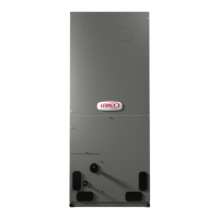
CBX25UHV‐060 Air Handler Performance (0 through 0.80 in. w.g. [0 — 200 Pa] External Static Pressure Range)
“ADJUST”
Jumper
Setting
Jumper Speed Positions
“HEAT” Speed First-Stage “COOL” Speed Second-Stage “COOL” Speed
1 2 3 4 1 2 3 4 1 2 3 4
cfm cfm cfm cfm cfm cfm cfm cfm cfm cfm cfm cfm
+ 1700 1930 2120 2275 1225 1410 1530 1690 1720 1930 2140 2270
NORM 1570 1760 1925 2100 1120 1260 1400 1540 1580 1765 1970 2100
– 1420 1595 1760 1920 1015 1160 1275 1390 1430 1625 1780 1890
NOTES
The effect of static pressure, filter and electric heater resistance is included in the air volumes listed.
First-stage cooling air volume is 70% of COOL (second-stage) speed setting. Continuous blower speed is approximately 50% of COOL speed setting.
Lennox Harmony III™ Zoning System applications minimum blower speed is 450 cfm.
Table 10. Merit
®
CBX25UHV, Thermostat and Single-Stage Outdoor Unit Operating Sequence
Operating Sequence System Demand System Response
System
Condition
Step
Thermostat Demand Relative Humidity
Com
pressor
Air
Handler
CFM
(COOL)
Comments
Y1 Y2 O G W1 W2 Status D
NO CALL FOR DEHUMIDIFICATION
Normal Operation 1 On On On Acceptable 24 VAC High 100%
Compressor and indoor air handler fol
low thermostat demand
BASIC MODE (only active on a Y1 thermostat demand)
Normal
Operation
1 On On On Acceptable 24 VAC High 100%
Thermostat energizes Y1 and de-ener
gizes D on a call for dehumidification
Dehumidification Call 2 On On On Demand 0 VAC High
60%/65
70%*
PRECISION MODE (operates independent of a Y1 thermostat demand)
Normal Operation 1 On On On Acceptable 24 VAC High 100%
Dehumidification mode begins when hu
midity is greater than set point
Dehumidification Call 2 On On On Demand 0 VAC High
60%/65%
70%*
Dehumidification Call
ONLY
1 On On On Demand 0 VAC High
60%/65%
70%*
Thermostat will try to maintain room hu
midity setpoint by allowing the room
space to maintain a cooler room ther
mostat setpoint**
Jumpers at indoor unit with a single stage outdoor unit
With Condensing unit - Y1 to Y2 and R to O
With Heat Pump - Y1 to Y2
* During dehumidification, cooling air handler speed is as follows: 70% of COOL cfm for 018, 024, 030; 65% for 036; 60% for 042, 048 and 060 units.
** Thermostat will maintain the room temperature up to 2°F (1.2°C) cooler than the room thermostat setting in precision mode.
 Loading...
