Page 41
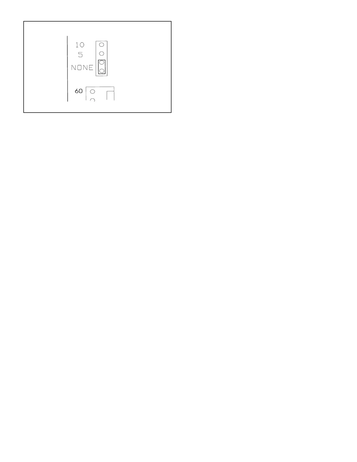
FIGURE 60
Humidier
Terminals are provided on the integrated ignition/blower
control for connection to a 120-volt humidier. The “HUM”
terminal is energized whenever the thermostat calls for
heat. See the furnace wiring diagram for specic connec-
tion information.
Electronic Air Cleaner
Terminals are provided on the integrated ignition/blower
control board for connection of a 120-volt electronic air
cleaner. The “EAC” terminal is energized whenever the
thermostat calls for heat, cooling, or continuous blower.
See furnace wiring diagram for specic connection infor-
mation.
Variable Speed Features
This furnace is equipped with a variable speed circulation
air blower motor that will deliver a constant airow within a
wide range of external static pressures. Other features of
this variable speed motor include:
Soft Start
The variable speed motor will slowly ramp up to normal
operating speed. This minimizes noise and increases
comfort by eliminating the initial blasts of air encountered
with standard motors.
Soft Stop
At the end of a cooling or heating cycle, the variable speed
motor will slowly ramp down after a short blower “o” de-
lay. If continuous blower operation has been selected, the
variable speed motor will slowly ramp down until it reach-
es the airow for that mode.
Passive and Active Dehumidication
Both the passive and active dehumidication methods de-
scribed below can be utilized on the same furnace.
Passive Dehumidication
For situations where humidity control is a problem, a
dehumidication feature has been built into the variable
speed motor. At the start of each cooling cycle, the vari-
able speed motor will run at 82% of the rated airow for
7.5 minutes. After 7.5 minutes has elapsed, the motor will
increase to 100% of the rated airow.
Active Dehumidication
To achieve additional dehumidication, clip the jumper
wire located below the DEHUM terminal on the integrat-
ed ignition/ blower control board and connect a humidity
control that opens on humidity rise to the DEHUM and R
terminals. The DEHUM terminal on the control board must
be connected to the normally closed contact of the hu-
midity control so that the board senses an open circuit on
high humidity. In this setup, the variable speed motor will
operate at a 30% reduction in the normal cooling airow
rate when there is a call for dehumidication.
Circulating Airow Adjustments
Cooling Mode
The units are factory set for the highest airow for each
model. Adjustments can be made to the cooling airow by
repositioning the jumper plug marked COOL – A, B, C, D
(see Figure 59). To determine what CFM the motor is de-
livering at any time, count the number of times the amber
LED on the control board ashes. Each ash signies 100
CFM; count the ashes and multiply by 100 to determine
the actual CFM delivered (for example: 5 ashes x 100 =
500 CFM).
Heating Mode
These units are factory set to run at the middle of the heat-
ing rise range as shown on the unit rating plate. If higher
or lower rise is desired, reposition the jumper plug marked
HEAT - A, B, C,(see Figure 59 and table on page 44 for
“Allowable Heating Speeds”. To determine what CFM the
motor is delivering at any time, count the number of times
the amber LED on the control board ashes. Each ash
signies 100 CFM; count the ashes and multiply by 100
to determine the actual CFM delivered (for example: 5
ashes x 100= 500.
Adjust Tap
Airow amounts may be increased or decreased by 10%
by moving the ADJUST jumper plug (see Figure 59) from
the NORM position to the (+) or (-) position. Changes to
the ADJUST tap will aect both cooling and heating air-
ows. The TEST position on the ADJUST tap is not used.
Continuous Blower Operation
The comfort level of the living space can be enhanced
when using this feature by allowing continuous circulation
of air between calls for cooling or heating. The circulation
of air occurs at half the full cooling airow rate.
To engage the continuous blower operation, place the fan
switch on the thermostat into the ON position. A call for fan
from the thermostat closes R to G on the ignition control
board. The control waits for a 1 second thermostat delay
before responding to the call for fan by ramping the circu-
lating blower up to 38% of the cooling speed. When the
call for continuous fan is satised, the control immediately
ramps down the circulating blower.
 Loading...