Do you have a question about the Lennox ML296UHV(X) Series and is the answer not in the manual?
Hazard warning regarding improper installation, adjustment, alteration, service, or maintenance.
Details heating performance specifications including input, output, and temperature rise for different models.
Blower performance data (cfm) for ML296UH045XV36B with bottom return air configuration.
Blower performance data (cfm) for ML296UH045XV36B with single side return air.
Blower performance data (cfm) for ML296UH070XV36B with bottom return air configuration.
Blower performance data (cfm) for ML296UH070XV36B with single side return air.
Blower performance data (cfm) for ML296UH070XV36B with side return air and optional base.
Blower performance data (cfm) for ML296UH090XV48C with bottom return air configuration.
Blower performance data (cfm) for ML296UH090XV48C with single side return air.
Blower performance data (cfm) for ML296UH110XV60C with bottom return air configuration.
Information on the integrated control board, diagnostics, LEDs, and thermostat operation.
Critical safety warning about disconnecting power and waiting for capacitors to discharge.
Details on the dual pressure switch and its role in proving inducer operation.
Safety precautions regarding the flammability and handling of solvent cements.
Important information regarding the use of PVC vs. ABS vent pipe and required cements.
Critical safety warning about potential ignition of PVC glue fumes during system checks.
Critical safety warning regarding carbon monoxide hazards when testing venting systems.
Important warning against using screens or perforated metal in vent terminations to prevent freeze-ups.
Caution regarding sizing intake openings when combustion air is drawn from spaces with exhaust fans.
Important warnings regarding vent termination obstructions and Canadian installation requirements.
Caution against using copper tubing or existing copper condensate lines for drainage.
Important note on venting combined furnace and evaporator coil drains for proper pressure switch operation.
Checks to perform before initial unit start-up, including electrical and gas connections.
Detailed steps for initiating heating operation, including gas valve and burner ignition.
Critical warning regarding fire or explosion risk if instructions are not followed exactly.
Step-by-step instructions for operating the gas valve safely.
Common issues and checks to perform if the unit fails to operate after start-up.
Cautionary notes regarding flexible gas connectors and torque limits for gas piping.
Procedure for testing gas lines for leaks and pressure integrity.
Method for measuring gas supply pressure using a manometer.
Procedure for measuring and comparing manifold pressure to specifications.
Safety instruction to connect a shut-off valve between manometer and gas tap.
Procedure for checking gas flow rate using the gas meter clocking chart.
Guidelines for ensuring proper combustion, including CO limits.
General safety warning for servicing, emphasizing electrical shock, fire, and explosion hazards.
Warning about ensuring the blower access panel is securely in place during operation.
Important notes regarding the impact of high-efficiency filters on system static pressure and performance.
Detailed steps for removing and cleaning the heat exchanger assembly.
Procedure for cleaning the burner assembly, including visual inspection and removal of blockages.
Critical warning against charging a cooling system while in passive or active dehumidification mode.


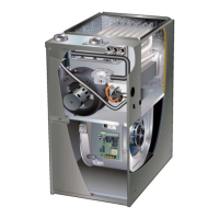
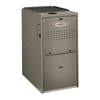

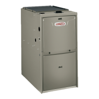
 Loading...