27
No. Dial Code Control
Scenario
Function ON OFF Note
7 SW2-4 2 Compressor/Auxiliary heat outdoor ambient
lockout
The compressor
will not operate
if the outdoor
temperature is
lower than the
temperature
represented by S3
[Default] The
heater will
not operate if
the outdoor
temperature is
greater than
the temperature
represented by S3
SW2-4 and S3
need to working
together
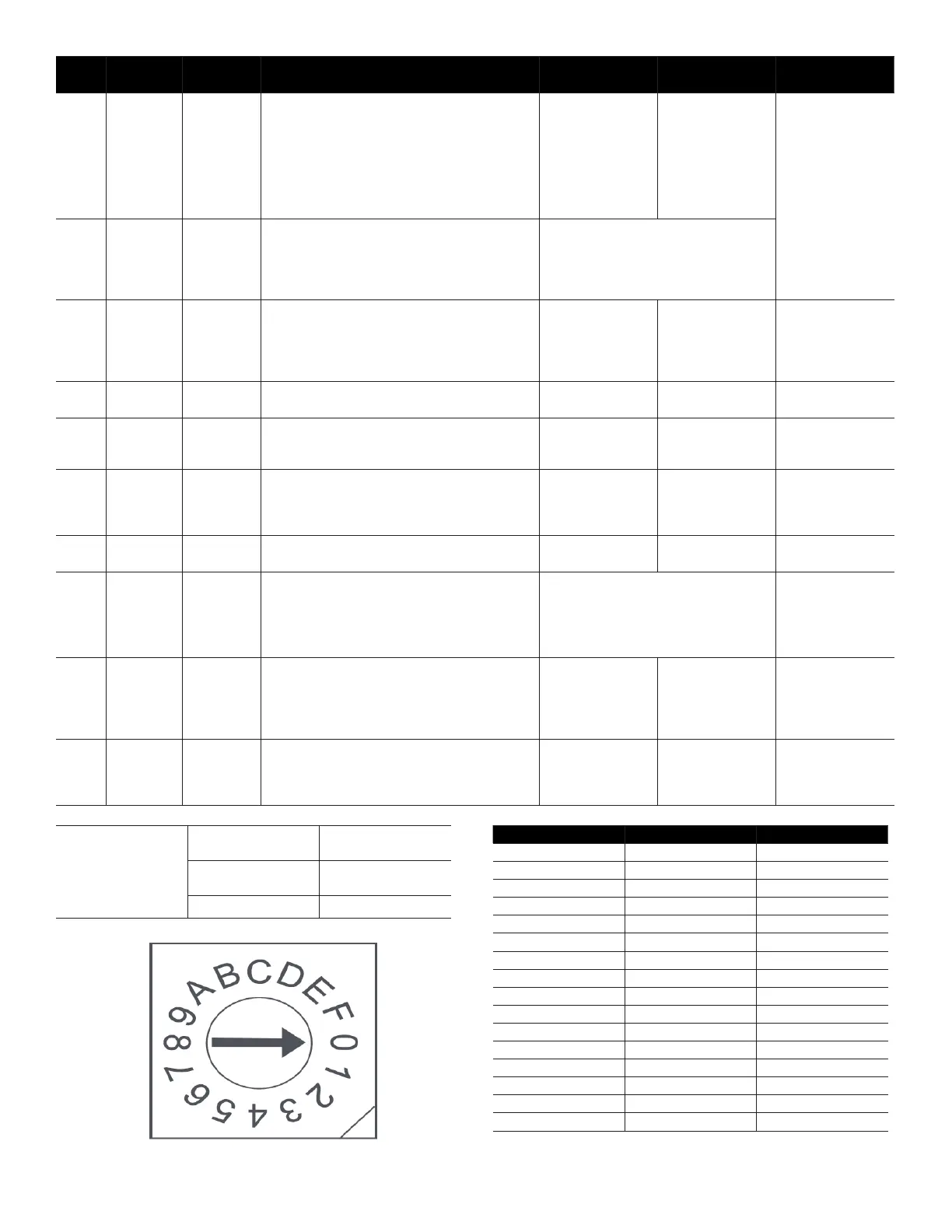
8 Rotary
Switch S3
2 Set outdoor temperature Limitation (for auxiliary
heating or compressor)
0 means that the temperature protection
is not turned on, the dial range is 1
through F, 1 equals -4°F and it increase
up to 46°F. See “Table 2. Dial Range
Table” on page 29.
9 SW3-1 1 Maximum continuous runtime allowed before
system automatically stages up capacity to
satisfy set point. This adds 1 to 5°F to the
user set point in the calculated control point to
increase capacity and satisfy user set point
30 minutes [Default] 90
minutes
10 SW3-2 1 Cooling and heating Y/Y2 temperature
dierential adjustment.
Compressor
slower speed
[Default] Faster
Compressor
Only aects
compressor
11 SW3-3 1 Compressor Running (demand working with
heat pump+ Electric heat)
Compressor
slower speed
[Default] Faster
Compressor
Only aects
compressor and
W2
12 SW3-3 2 Temperature dierential to activate second
stage auxiliary heating(the GAP of T1 and Ts)
Wire controller demand with heat pump+Electric
heat working together
4°F (2°C) [Default] 6°F (3°C)
13 SW3-4 1,3 Fan speed of cooling mode when 24V
Thermostat is applied for.
Turbo High
14 SW4 1,2,3 Electric heat nominal CFM adjustment Available settings are 000/001/010/011.
Each digit corresponds an individual
switch position.
For example [SW4-1 OFF, SW4-2 ON,
SW4 -3 OFF] = 010
15 S4-1 1,3 Default ON [Default] For
single stage
supplemental heat,
W1 and W2 are
connected
For dual stage
supplemental
heat, W1 and W2
are controlled
independently
16 S4-2 1,3 DH function selection [Default]
Dehumidication
control not
available
Dehumidication
feature is enabled
through thermostat
Control Scenario
24V Thermostat,
S1 + S2
1
Wired Controller
S1 + S2
2
Full 24V 3
S3 S3 (°F) S3 (°C)
0 OFF OFF
1 -4 -20
2 0 -18
3 3 -16
4 7 -14
5 10 -12
6 14 -10
7 18 -8
8 21 -6
9 25 -4
A 28 -2
B 32 0
C 36 2
D 39 4
E 43 6
F 46 8
Table 3. Dial Range Table
 Loading...