EasyManua.ls Logo

Lennox SCA Series User Manual

Lennox SCA Series
53 pages
To Next Page IconTo Next Page
Page #1 background imageLoading...
Page #1 background image
2007 Lennox Industries Inc.
Litho U.S.A.
Page 1
Corp. 0717−L5
SCA/SCB SERIES
Service Literature
10, 20 & 24 ton
35.2, 70.4 & 84.4 kW
Revised 10−2010
SCA/SCB
The SCA120, 240, 10 and 20 ton and SCB 288 24 ton, (35.2,
70.4 and 84.4 kW) units, are configure to order units (CTO)
with a wide selection of factory installed options. The SCA120
has a cooling capacity of 123,000 Btuh and the SCA240 has
gross a cooling capacity of 242,000 Btuh and the SCB has a
gross cooling capacity of 296,000 Btuh. All models are avai-
labe with factory installed multiple staged air volume (MSAV).
Units are designed for R410A refrigerant. See unit name-
plate. Operating pressures and pressure switch settings
are significantly higher than R22 charged units. Service
equipment must be rated for R410A.
Optional electric heat is factory installed in SCA units. Electric
heat operates in single or multiple stages depending on the
kW input size. 15 kW to 60 kW heat sections are available for
the SCA120 and 30, 60 and 90 kW heat sections are avail-
able for the SCA240/SCB288. SCA120 units utilize two com-
pressors, while SCA240/SCB288 units utilize four.
Information contained in this manual is intended for use by
qualified service technicians only. All specifications are sub-
ject to change. Procedures outlined in this manual are pre-
sented as a recommendation only and do not supersede or
replace local or state codes.
If the unit must be lifted for service, rig unit by attaching four
cables to the holes located in the unit base rail (two holes at
each corner). Refer to the installation instructions for the prop-
er rigging technique.
WARNING
Improper installation, adjustment, alteration, service
or maintenance can cause property damage, person-
al injury or loss of life. Installation and service must
be performed by a qualified installer or service
agency.
WARNING
Electric shock hazard. Can cause injury
or death. Before attempting to perform
any service or maintenance, turn the
electrical power to unit OFF at discon-
nect switch(es). Unit may have multiple
power supplies.
CAUTION
Danger of sharp metallic edges. Can cause injury.
Take care when servicing unit to avoid accidental
contact with sharp edges.
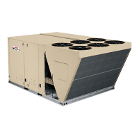
SCA120
SCA240/SCB288
Table of Contents
Options / Accessories Page 2. . . . . . . . . . . . . . .
Specifications Page 4. . . . . . . . . . . . . . . . . . . . . .
Blower Data Page 8. . . . . . . . . . . . . . . . . . . . . . .
Electrical / Electric Heat Data Page 12. . . . . . . .
Parts Arrangement Page 15. . . . . . . . . . . . . . . . .
I Unit Components Page 18. . . . . . . . . . . . . . . . . .
II Placement and Installation Page 36. . . . . . . . .
III Charging Page 36. . . . . . . . . . . . . . . . . . . . . . . .
IV System Service Checks Page 38. . . . . . . . . .
V Maintenance Page 38. . . . . . . . . . . . . . . . . . . . .
VI Accessories Page 39. . . . . . . . . . . . . . . . . . .
VII Wiring and Operation Sequence Page 42. . .
Question and Answer IconNeed help?

Do you have a question about the Lennox SCA Series and is the answer not in the manual?

Lennox SCA Series Specifications

General IconGeneral
SEERUp to 16
RefrigerantR-410A
Operating Voltage (VAC)208/230
Compressor TypeScroll
Cooling Capacity (BTU/h)18, 000 - 60, 000

Summary

OPTIONS / ACCESSORIES

SPECIFICATIONS

General Unit & Cooling Specs

Covers general data, cooling performance, refrigerant, and electric heat options.

Component Specifications

Details specs for compressors, coils, fans, blowers, and filters.

Electrical Characteristics

Outlines voltage and frequency ratings for electrical systems.

BLOWER DATA

SCA120 Blower Performance

Presents air volume vs. static pressure and BHP for SCA120.

SCA240 Blower Performance

Presents air volume vs. static pressure and BHP for SCA240.

SCB288 Blower Performance

Presents air volume vs. static pressure and BHP for SCB288.

Blower Drive Kit Specifications

Details specifications for CAV and MSAV blower drive kits.

Power Exhaust Fans Performance

Lists static pressure vs. air volume for power exhaust fans.

ELECTRICAL DATA

SCA120 Electrical & Heat Data

Electrical ratings, motor data, and electric heat protection for SCA120.

SCA240 Electrical & Heat Data

Electrical ratings, motor data, and electric heat protection for SCA240.

SCB288 Electrical & Heat Data

Electrical ratings, motor data, and electric heat protection for SCB288.

PARTS ARRANGEMENT

SCA120 Parts Arrangement

Diagram showing component locations for the SCA120 unit.

SCA240/SCB288 Parts Arrangement

Diagram showing component locations for SCA240/SCB288 units.

UNIT COMPONENTS

Electrostatic Discharge (ESD) Precautions

Safety precautions to prevent damage to electronic components from ESD.

Control Box Components

Details components found within the control box.

Cooling Components

Describes compressors, pressure switches, and ambient switches.

Blower Compartment

Details the location and features of the blower compartment and wheels.

PLACEMENT AND INSTALLATION

Three Phase Compressor Voltage Phasing

Ensures correct rotation and operation of three-phase compressors.

R410A Refrigerant

Information on R410A refrigerant, pressures, and gauge requirements.

CHARGING

Normal Operating Pressures

Provides tables of normal operating pressures based on outdoor temperature.

Approach Method - AHRI Testing

Details how to compare liquid temperature to ambient temperature for charge verification.

MAINTENANCE

Filter and Coil Maintenance

Procedures for maintaining filters, evaporator, and condenser coils.

Blower and Electrical Checks

Instructions for blower wheel inspection and electrical system checks.

ACCESSORIES

Roof Mounting Frames

Details mounting frame requirements for SCA120 and SCA240/SCB288 units.

Economizer

Explains economizer operation modes and controls.

Gravity Exhaust Dampers

Requirements for gravity exhaust dampers when using economizers or power exhaust.

Outdoor Air Dampers

Describes manually operated outdoor air dampers for 240/288 units.

Power Exhaust Fans

Application and location of power exhaust fans.

WIRING DIAGRAMS AND SEQUENCE OF OPERATION

SCA120 UNIT DIAGRAM

Wiring diagram for the SCA120 unit.

SCA120 SEQUENCE OF OPERATION

Step-by-step operation for SCA120 cooling and blower functions.

Sequence of Operation SCA240/SCB288

Operation sequence for SCA240/SCB288 cooling, blower, and economizer.

Economizer Wiring Diagram

Wiring diagram for the economizer system.

Related product manuals