Page 57
SGH/SCH036, 060, 120, 240
A
B
C
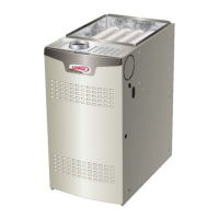
FIGURE 43
IGNITOR AND SENSOR POSITION
120, 240 UNITS
TOP VIEW
SIDE VIEW IGNITOR SIDE VIEW SENSOR
1-3/4”
(45mm)
3/8”
(10mm)
1-3/8”
(35mm)
BURNER BOX
Gas Flow Gas Flow
13/16”
(21mm)
A
B
C
IGNITOR SENSOR
Cleaning Combustion Air Inducer
1- Shut off power supply and gas to unit.
2- Disconnect pressure switch air tubing from combustion
air inducer port.
3- Remove and retain screws securing combustion air
inducer to flue box. Remove vent connector. See figure
32 for 036 and 060 units and figure 44 for 120, and 240
units.
4- Clean blower wheel blades with a small brush and wipe
off any dust from housing. Clean accumulated dust
from front of flue box cover.
5- Return combustion air blower motor and vent connector
to original location and secure with retained screws. It is
recommended that the combustion air inducer gasket be
replaced during reassembly.
6- Clean combustion air inlet louvers on heat access
panel using a small brush.
E-Flue Passageway and Flue Box (SG Units)
1- Remove combustion air inducer assembly as
described in section D.
2- Remove flue box cover. Clean with a wire brush as
required.
3- Clean tubes with a wire brush.
4- Reassemble the unit. The flue box cover gasket and
combustion air inducer gasket should also be replaced
during reassembly.
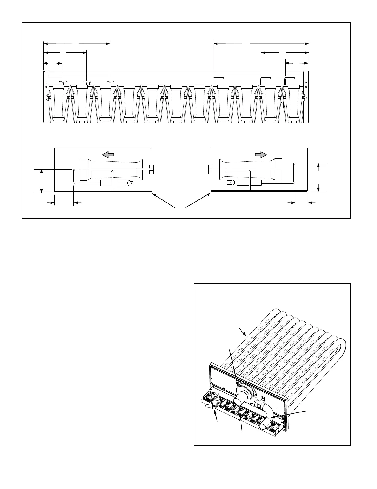
HEAT EXCHANGER ASSEMBLY
120, 240
FIGURE 44
BURNER
COMBUSTION
AIR INDUCER
VENT
CONNECTOR
GAS VALVE
HEAT
EXCHANGER
TUBE
 Loading...