Page 25
DIP Switch Settings
NOTE - All communicating settings are set at the commu-
nicating thermostat. See thermostat installation instruc-
tion. In a communication system all DIP switch and clippa-
ble link settings are ignored. For conventional thermostats
proceed with DIP switch and clippable link settings as out-
lined in the following.
Heating Operation DIP Switch Settings
Switch 1 -- Thermostat Selection -- This unit may be
used with either a single-stage or two-stage thermostat.
The thermostat selection is made using a DIP switch
which must be properly positioned for the particular appli-
cation. The DIP switch is factory-positioned for use with a
twostage thermostat. If a single-stage thermostat is to be
used, the DIP switch must be repositioned.
a. Select “OFF” for two-stage heating operation controlled by a
two-stage heating thermostat (factory setting);
b. Select “ON” for two-stage heating operation controlled by
a single-stage heating thermostat. This setting provides a
timed delay before second-stage heat is initiated.
Switch 2 -- Second Stage Delay (Used with Single-
Stage Thermostat Only) -- This switch is used to de-
termine the second stage on delay when a single-stage
thermostat is being used. The switch is factory-set in the
OFF position, which provides a 7-minute delay before
secondstage heat is initiated. If the switch is toggled to
the ON position, it will provide a 12-minute delay before
secondstage heat is initiated. This switch is only activated
when the thermostat selector jumper is positioned for SIN-
GLEstage thermostat use.
Switches 3 and 4 -- Blower-O Delay -- The blower-on
delay of 30 seconds is not adjustable. The blower-o de-
lay (time that the blower operates after the heating de-
mand has been satised) can be adjusted by moving
switches 3 and 4 on the integrated control. The unit is
shipped from the factory with a blower-o delay of 90 sec-
onds. The blower o delay aects comfort and is adjust-
able to satisfy individual applications. Adjust the blower
o delay to achieve a supply air temperature between 90°
and 110°F at the exact moment that the blower is de-en-
ergized. Longer o delay settings provide lower supply
air temperatures; shorter settings provide higher supply
air temperatures.TABLE 6 provides the blower o timings
that will result from dierent switch settings.
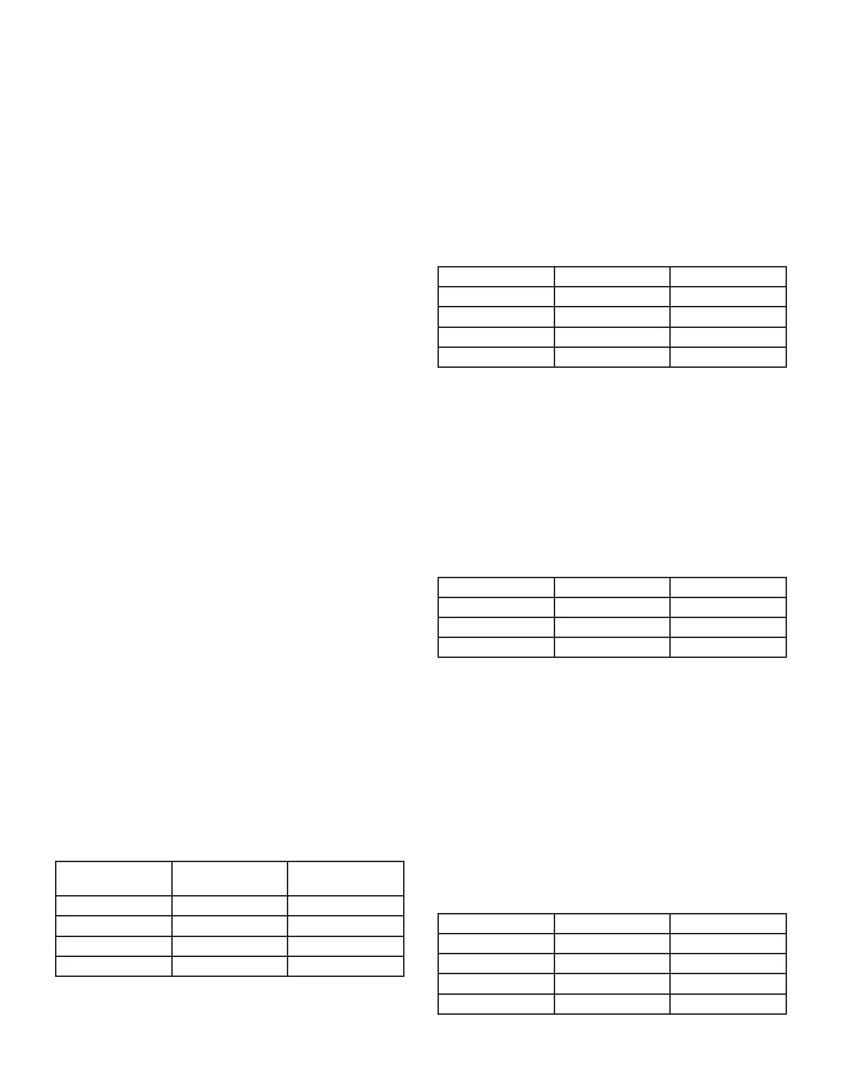
TABLE 6
Blower O Delay Switch Settings
Blower O Delay
(Seconds)
Switch 3 Switch 4
60 On O
90 (factory) O O
120 O O
180 On O
Indoor Blower Operation DIP Switch Settings
Switches 5 and 6 -- Cooling Mode Blower Speed --
The unit is shipped from the factory with the dip switch-
es positioned for high speed (4) indoor blower motor op-
eration during the cooling mode. TABLE 7 provides the
cooling mode blower speeds that will result from dierent
switch settings. Switches 5 and 6 set the blower cfm for
secondstage cool. The integrated control automatically
ramps down to 70% of the second-stage cfm for rst-stage
cfm. Refer to blower tables for corresponding cfm values.
TABLE 7
Cooling Mode Blower Speeds
Speed Switch 5 Switch 6
Low On On
Medium Low O On
Medium High On O
High (Factory) O O
Switches 7 and 8 -- Cooling Blower Speed Adjustment
-- The unit is shipped from the factory with the dip switches
positioned for NORMAL (no) adjustment. The dip switches
may be positioned to adjust the blower speed by +10% or
-10% to better suit the application. TABLE 8 below pro-
vides blower speed adjustments that will result from dier-
ent switch settings. Refer to blower tables for correspond-
ing cfm values.
TABLE 8
Cooling Blower Speed Adjustment
Adjustment Switch 7 Switch 8
+10% (approx.) On O
Factory Default O O
-10% (approx.) O On
Switches 9 and 10 -- Cooling Mode Blower Speed
Ramping -- Blower speed ramping may be used to en-
hance dehumidication performance. The switches are
factory set at option A which has the greatest eect on de-
humidication performance. TABLE 9 provides the cooling
mode blower speed ramping options that will result from
dierent switch settings. The cooling mode blower speed
ramping options are detailed below.
NOTE - The o portion of the selected ramp prole also
applies during heat pump operation in dual fuel applica-
tions.
TABLE 9
Cooling Mode Speed Ramping
Ramping Option Switch 9 Switch 10
A (factory) O O
B O On
C On O
D On On
 Loading...


