Page 26
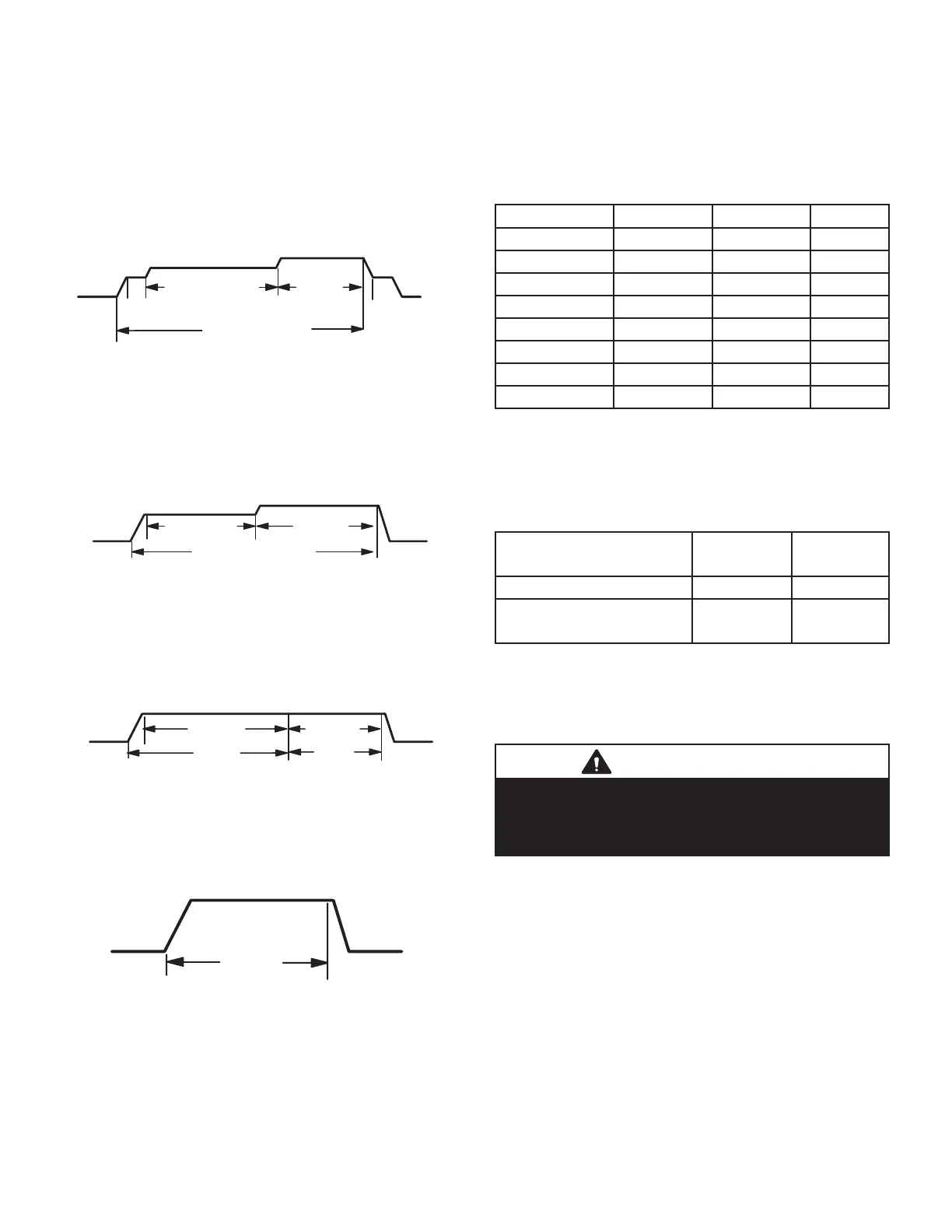
Ramping Option A (Factory Selection)
• Motor runs at 50% for 30 seconds.
• Motor then runs at 82% for approximately 7-1/2
minutes.
• If demand has not been satised after 7-1/2 min-
utes, motor runs at 100% until demand is satised.
• Once demand is met, motor runs at 50% for 30
seconds then ramps down to stop.
OFF
1/2 MIN
50% CFM
COMPRESSOR DEMAND
7 1/2 MIN
82% CFM
100%
CFM
1/2 MIN
50% CFM
Ramping Option B
• Motor runs at 82% for approximately 7-1/2 minutes.
If demand has not been satised after 7-1/2 min-
utes, motor runs at 100% until demand is satised.
• Once demand is met, motor ramps down to stop.
OFF
OFF
82%CFM
100% CFM
COMPRESSOR DEMAND
7 1/2 MIN
Ramping Option C
• Motor runs at 100% until demand is satised.
• Once demand is met, motor runs at 100% for 45
seconds then ramps down to stop.
OFF
100% CFM
100% CFM
45 SEC.
COMPRESSOR
DEMAND
Ramping Option D
• Motor runs at 100% until demand is satised.
• Once demand is met, motor ramps down to stop.
OFFOFF
100% CFM
COMPRESSOR
DEMAND
Switches 11, 12 and 13 -- Heating Mode Blower Speed
The switches are factory set to the OFF position which
provides factory default heat speed. Refer to TABLE 10 for
switches 11, 12 and 13 that provided the corresponding
increases or decrease to both high and low heat demand.
TABLE 10
Heating Mode Blower Speeds
Heat Speed Switch 11 Switch 12 Switch 13
Increase 24% On On On
Increase 18% On On O
Increase 12% On O On
Increase 6% On O O
Factory Default O O O
Decrease 6% O O On
Decrease 12% O On O
Decrease 18% O On On
Switches 14 and 15 -- Continuous Blower Speed
TABLE 11 provides continuous blower speed adjustments
that will result from dierent switch settings.
TABLE 11
Continuous Blower Speed
Continuous
Blower Speed
Switch 14 Switch 15
28% of High Cool Speed O On
38% of High Cool Speed
(Factory Setting)
O O
On-Board Links
Note: Communicating systems with a conventional out-
door unit (non-communicating), the on-board clippable
links must be set to properly congure the system.
IMPORTANT
Carefully review all conguration information
provided. Failure to properly set DIP switches,
jumpers and on-board links can result in improper
operation!
On-Board Link W914 Dehum or Harmony (R to DS)
On-board link W914, is a clippable connection between
terminals R and DS on the integrated control. W914 must
be cut when the furnace is installed with either the Harmo-
ny III zone control or a thermostat which features humidity
control. If the link is left intact the PMW signal from the
Harmony III control will be blocked and also lead to con-
trol damage. Refer to TABLE 12 for operation sequence
in applications including SL280DFV, a thermostat which
features humidity control and a single-speed outdoor unit.
TABLE 13 gives the operation sequence in applications
with a two-speed outdoor unit.
 Loading...


