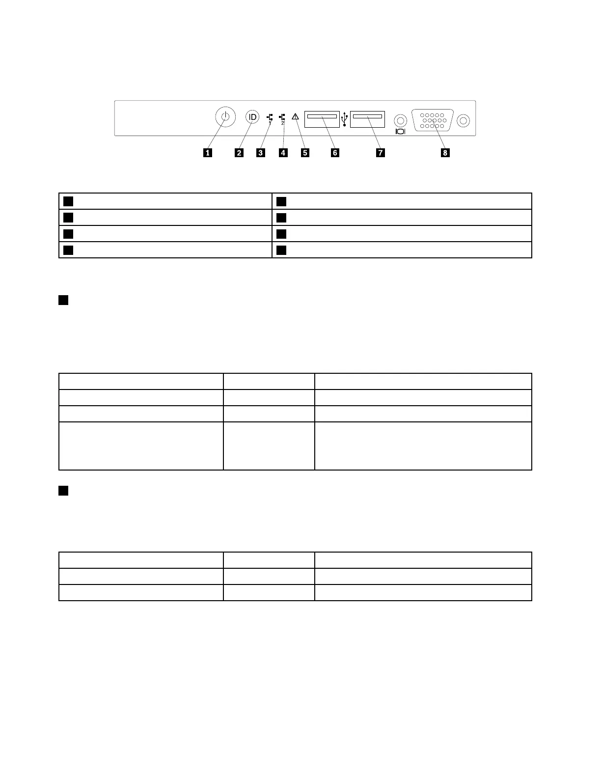
Thefollowingillustrationshowsthecontrols,connectors,andLEDsonthefrontpaneloftheserver.
Figure11.Frontpanel
1PowerbuttonwithpowerstatusLED
5SystemerrorLED
2IDbuttonwithIDLED
6FrontUSBconnector1
3NetworkInterfaceController(NIC)1statusLED7FrontUSBconnector2
4NIC2statusLED8FrontVGADB-15connector
Note:ThefrontVGADB-15connectorisonlyavailableinservermodelswith2.5-inchharddiskdrives.
1PowerbuttonwithpowerstatusLED
Youcanpressthepowerbuttontoturnontheserverwhenyoufinishsettinguptheserver.Youalsocan
holdthepowerbuttonforseveralsecondstoturnofftheserverifyoucannotturnofftheserverfromthe
operatingsystem.SeeChapter4“Turningonandturningofftheserver”onpage49.ThepowerstatusLED
helpsyoutodeterminethecurrentpowerstatus.
PowerstatusLED
Color
Description
OnGreen
Theserverison.
Off
None
Theserverisoff.
Blinking
GreenTheserverisinACPIS1mode,whichalsoisknown
asPowerOnSuspend(POS)mode.Inthismode,the
microprocessorisnotworkingwhileotherhardware
devicesarestillworking.
2IDbuttonwithIDLED
WhenyoupresstheIDbutton,theIDLEDsonboththefrontandrearoftheserverarelittohelpyoulocate
theserveramongotherservers.YoualsocanturnontheIDLEDsusingaremotemanagementprogram
forserverpresencedetection.
IDLED
Color
Description
On
Blue
Theserverisidentified.
Off
None
TheIDLEDisnotinuseortheserverisnotidentified.
20ThinkServerRD340UserGuideandHardwareMaintenanceManual