9 NMI button
Press this button to force a nonmaskable interrupt to the processor. You might have to use a pen or the end
of a straightened paper clip to press the button. You can also use it to force a blue-screen memory dump.
Use this button only when you are directed to do so by Lenovo Support.
10 PCIe slots
There are four PCIe slots on the system board to install appropriate PCIe adapters. For information about the
PCIe slots, see
“Specifications” on page 3.
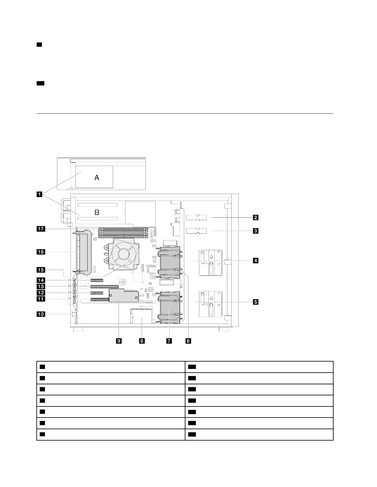
Side view
Follow the instructions in this section to locate the components from the side of the server.
Note: Depending on the configuration, your server might be slightly different from the image.
Table 8. Components on the server models side view
1 Power supply cage 10 Intrusion switch
2 Upper ODD drive bay 11 PCIe Slot 4
3 Lower ODD/tape drive bay 12 PCIe Slot 3
4 Upper storage drive cage
13 PCIe Slot 2
5 Lower storage drive cage
14 PCIe Slot 1
6 Front system fan 1
15 Processor and heat sink
7 Front system fan 2 16 Rear system fan
22 ThinkSystem ST250 V3 System Configuration Guide

 Loading...


