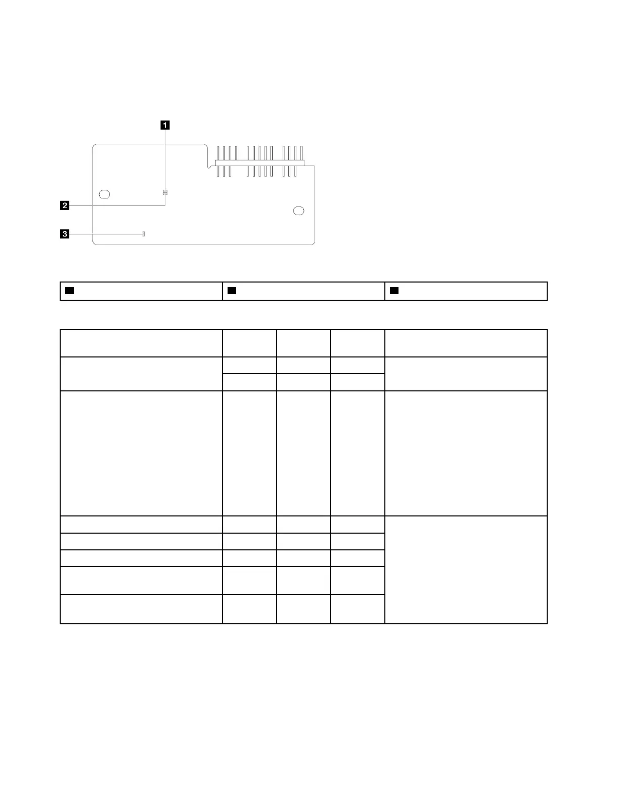
Firmware and RoT security module LEDs
The following illustrations show the light-emitting diodes (LEDs) on the ThinkSystem V3 Firmware and Root
of Trust Security Module (Firmware and RoT Security Module).
Figure 18. LEDs on the firmware and RoT security module
1 AP0 LED (Green) 2 AP1 LED (Green) 3 Fatal Error LED (Amber)
Table 14. LEDs description
Scenario AP0 LED AP1 LED
Fatal
Error LED Actions
RoT security module fatal firmware
failure
Off Off On Replace the firmware and RoT
security module.
Blink
N/A On
No system power (FPGA heartbeat
LED off)
Off Off Off If the AC power is on, but the system
board does not have power, then:
1. Check the power supply unit
(PSU) or power distribution
board. If the PSU or power
distribution board has any error,
replace it.
2. If the PSU or power distribution
board is good, replace the
system board.
XCC firmware recoverable error
Blink
N/A Off
Information only. No action is
required.
XCC firmware is recovered from error On N/A Off
UEFI firmware authentication failure N/A
Blink
Off
UEFI firmware is recovered from
authentication failure
N/A On Off
System is OK (FPGA heartbeat LED is
On)
On On Off
XCC system management port and Ethernet port LEDs
This topic provides information on LEDs of XCC system management port and Ethernet port.
The following table describes the problems that are indicated by LEDs on XCC system management port and
Ethernet port.
36
ThinkSystem ST250 V3 System Configuration Guide

 Loading...


