Electrical installation
Wiring to a host
6
EDK82ZAFPC-010 DE/EN/FR 6.0
55
H2 VerdrahtLeitrechner-PBS_leitungsspezifikation
The connection of the PROFIBUS bus system is shown in the general layout drawing.
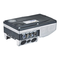
8200vector
+
E82ZAFPC010
8200vector
+
E82ZAFPC010
8200vector
+
E82ZAFPC010
3 3 3
1
2 2 2
0m
1200m
E82ZAFP005
Fig. 1 Example: PROFIBUS with RS485 wiring (without repeater)
No. Element Note
1 Host E.g. PC or PLC with PROFIBUS master interface module
2 Bus cable Connects the PROFIBUS master interface module to the function
modules.
The baud rate depends on the length of the bus cable (
57).
3 PROFIBUS slave Applicable standard device (
45)with function module
Activate bus terminating resistors at the first and last physical
node (
68).
Note!
When using a repeater, max. 125 nodes can communicate via the PROFIBUS.