Control connections
3
8
MA DrivePLC DE/EN/FR 1.0
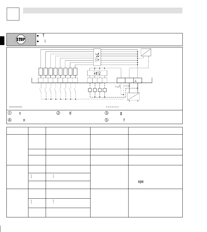
Terminal strips on the top of the instrument
l
The Drive PLC can only be connected to a supply voltage of max. + 30 V DC !
l
Higher voltages, or AC, will destroy the instrument !
plc002
X3 I8
I4 I7
I3 I6
I2
I5
I1
3K
3K
3K
3K
3K
3K
3K
3K
X2 O1 O2 O3 O4
+
~~
-
X1 +O24
+24
24
Z Z Z Z
Abb. 1-18
Connection required Possible connection
Encoder
ó
Load
ì
Emergency off
ö
External DC supply voltage
ú
Supply for control electronics
Terminal Use level Data
Vol ta ge
supply
X1/
⊥
24 0 V of supply voltage,
ground for digital inputs
and outputs
- -
X1/+ 24 Supply voltage +18 VDC ... 30 VDC -
X1/+ O24 Supply voltage for digital
outputs
+18 VDC ... 30 VDC -
Digital
X3/I1 Freely assignable input 1
Input current: 8 mA at 24 V
npu
s
ac
e
LOW: 0 V ... +4 V
eading and p
ocessing the
inputs: shortest reading cycle: 1
X3/I8 Freely assignable input 8
HIGH: + 13 V ... + 30 V
ms (depending on the site where
the process map is generated)
Digital
outputs
X2/O1 Freely assignable output 1
Load capacity: max. 1 A per
out
ut
u
u
HIGH acti
e
LOW: 0 V ... +4 V
u
u
Updating the outputs: shortest
u
date c
cle is 1 ms
de
endin
X2/O4
HIGH: + 13
... +30
u
onthesitewheretheprocess
map is generated)
 Loading...