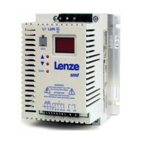
How to fix communication error on Lenze ESMD153L4TXA Inverter?
- TTroy MooreSep 1, 2025
If the Lenze Inverter reports a communication error, it could be due to the serial timer timing out. In this case, check the serial link connections.
How to fix communication error on Lenze ESMD153L4TXA Inverter?
If the Lenze Inverter reports a communication error, it could be due to the serial timer timing out. In this case, check the serial link connections.
How to troubleshoot Remote keypad fault on Lenze Inverter?
If the Lenze Inverter shows 'Remote keypad fault', it means the remote keypad is disconnected. To resolve this, check the remote keypad connections.
What causes motor overload on Lenze Inverter?
If the Lenze Inverter displays a motor overload (I2t overload), it means the motor is thermally overloaded. This can be due to: * Impermissible continuous current. * Frequent or excessively long acceleration processes. To resolve this: * Check the controller selection. * Check the setting of c20.
What does it mean when Lenze DC Drives reach the current limit?
Reaching the current limit in Lenze DC Drives indicates a controllable overload, which is managed automatically.
What causes overvoltage on DC bus in Lenze DC Drives and how to fix it?
Overvoltage on the DC bus in Lenze DC Drives can be caused by several factors. It may be due to mains voltage being too high, so you should check the mains voltage. Another cause can be an excessively short deceleration time or the motor operating in generator mode; in this case, increase the deceleration time or use a dynamic braking option. Finally, earth leakage on the motor side can also cause this issue, so check the motor and motor cable, separating the motor from the controller.
What to do if Lenze DC Drives show data on EPM not valid?
If Lenze DC Drives indicate that the data on the EPM is not valid, it means the data is not valid for the controller. Use an EPM providing valid data or load the Lenze setting.
What causes automatic start to be inhibited in Lenze DC Drives?
If automatic start is inhibited in Lenze DC Drives, it is because c42 = 0. You should apply a LOW-HIGH signal change at terminal 28.
How to resolve dynamic braking fault in Lenze DC Drives?
A dynamic braking fault in Lenze DC Drives typically means that the dynamic braking resistors are overheating. To resolve this, increase the deceleration time.
What to do if Lenze DC Drives show undervoltage on DC bus?
If Lenze DC Drives show undervoltage on the DC bus, it could be because the mains voltage is too low. Check the mains voltage.
What to do if Lenze DC Drives have controller overtemperature?
If the controller has an overtemperature, it means the controller is too hot inside. To resolve this, reduce the controller load and improve cooling.
General safety precautions for Lenze controllers, covering risks from live parts and hot surfaces.
Guidelines for using drive controllers in machines and compliance with EC directives like Machinery Directive.
Proper handling, avoiding mechanical stress, and preventing damage to electronic components during installation.
Observing national regulations and appropriate procedures for electrical installation, including cable and PE connection.
Ensuring systems have monitoring/protection devices and following operational safety rules like closing covers.
Policy on using inverter products with explosion proof motors, including liability and risk assumption.
Explanation of pictographs (Danger, Warning, Stop, Note) and their consequences if ignored.
Conformity, approvals, environmental conditions, and operating parameters for the inverter.
Electrical ratings including input voltage, current, and output current for various inverter models.
Guidelines for physical mounting, dimensions, and environmental considerations for the inverter.
Procedures for wiring, EMC requirements, fuses, cable cross-sections, and connection diagrams.
How to navigate the controller interface to set and change parameters.
Information about the EPM for storing, transferring, and managing parameter settings.
Detailed description of parameter codes, possible settings, and important notes for configuration.


