M
Mrs. Amanda FreemanSep 1, 2025
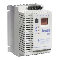
How to fix communication error on Lenze ESMD371L4TXA?
- CChristopher LindseySep 1, 2025
If the Lenze Inverter reports a communication error, it could be due to the serial timer timing out. In this case, check the serial link connections.