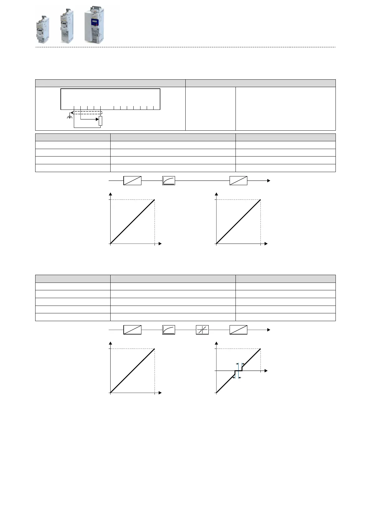
14.14.1.1 Example 1: Input range 0 ... 10 V ≡ seng range 0 ... 50 Hz
In this conguraon, for instance, a frequency setpoint between 0 and 50 Hz can be set with a
potenometer connected to the analog input.
Connecon plan funcon
GND
AI1
AI2
AO1
10V
24V
DI1
DI2
DI3
DI4
DI5
DO1
X3
1k ...10k
0 ... 10 V
R1
Potenometer R1 Frequency setpoint selecon
(Input voltage 1 V ≡ 5 Hz)
Parameter Name Seng for this example
0x2636:001 (P430.01) Analog input 1: Input range 0 ... 10 VDC [0]
0x2636:002 (P430.02) Analog input 1: Min frequency value 0.0 Hz
0x2636:003 (P430.03) Analog input 1: Max frequency value 50.0 Hz
0x2636:006 (P430.06) Analog input 1: Filter me 10 ms
100
0
50
[Hz]
[%]
0
10
0
100
[%]
[V]
0
AI1
%
Hz
V
%
10 ms0 ... 10 VDC 0 ... 50 Hz
14.14.1.2 Example 2: Input range 0 ... 10 V ≡ seng range -40 ... +40 Hz
In this example, a bipolar seng range and a dead band with 2 % are congured.
Parameter Name Seng for this example
0x2636:001 (P430.01) Analog input 1: Input range 0 ... 10 VDC [0]
0x2636:002 (P430.02) Analog input 1: Min frequency value -40.0 Hz
0x2636:003 (P430.03) Analog input 1: Max frequency value 40.0 Hz
0x2636:006 (P430.06) Analog input 1: Filter me 10 ms
0x2636:007 (P430.07) Analog input 1: Dead band 2.0 %
10
0
100
[%]
[V]
0
100
0
40
-40
2 %
[Hz]
[%]
2 %
0
AI1
%
Hz
V
%
10 ms 2 %0 ... 10 VDC -40 ... 40 Hz
Flexible I/O conguraon
Conguraon of analog inputs
Analog input 1
599
 Loading...


