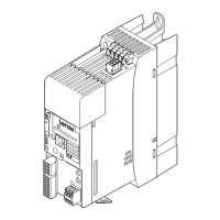
Electrical installation
Basic circuit diagram
4
l
56
EDKLCMZ3024−SPS DE/EN 4.0
4.2 Basic circuit diagram
M
3~
- +
~ ~ S1 S2
1 2 3 4 5 6 1 2 3
Th
BRK1
X21
ca
U1
V1
W1
1
2 3
a
X10
S0
STO
BS1
PE
4 * 2,5 mm
2
PE
PE
F1
16 A
K2
3/PE AC 400 V
PE
PE
L3
L2
L1
M
3~
- +
~ ~ S1 S2
1 2 3 4 5 6 1 2 3
Th
BRK2
a
U1
V1
W1
BS2
FE
PE
PE
X60
FE
FE
PROFIsafe
PROFIsafe
PE
X32
X31
X22
1
2 3
b
μ
C
X11
~
24 V DC
+
-
N
K1
c
lcu122_001
F1 Cable protection (observe cable protection standards for fuse dimensioning!)
K1 Main contactor
K2 Contactor for 24 V supply
FE Functional earth for compliance with EMC conditions, prevents compensating currents
via the PROFIBUS cable shield
S0 Service switch
BS1 Brake control, motor 1
BRK1 Spring−operated brake, motor 1
BS2 Brake control, motor 2
BRK2 Spring−operated brake, motor 2
Th PTC thermistor (PTC) or thermal contact (NC contact)
STO Safe torque off by means of PROFIsafe