Electrical installation
Motor connection
4
l
58
EDKLCMZ3024−SPS DE/EN 4.0
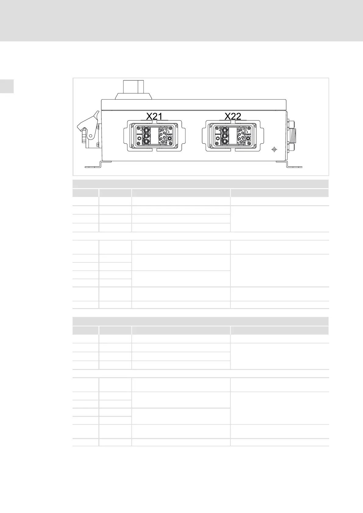
4.4 Motor connection
lcu122_000d
X21 − Motor 1 connection
Pin Connection Description Data
Connector: Socket, Harting HAN−Modular
a1 U1 Phase U1
Output voltage = mains voltage
Max. continuous output current
dependent on type
(sum of all output currents)
a2 V1 Phase V1
a3 W1 Phase W1
c1 +PTC Motor temperature monitoring PTC thermistor (PTC) or thermal contact
(NC contact)
c2 ~
Brake rectifier supply voltage The brake rectifier is installed in the motor
terminal box
c3 ~
c4 S1
Switch for disconnection on the DC side
c5 S2
c6 −PTC Motor temperature monitoring PTC thermistor (PTC) or thermal contact
(NC contact)
+ PE PE conductor
X22 − Motor 2 connection
Pin Connection Description Data
Connector: Socket, Harting HAN−Modular
a1 U1 Phase U1
Output voltage = mains voltage
Max. continuous output current
dependent on type
(sum of all output currents)
a2 V1 Phase V1
a3 W1 Phase W1
c1 +PTC Motor temperature monitoring PTC thermistor (PTC) or thermal contact
(NC contact)
c2 ~
Brake rectifier supply voltage The brake rectifier is installed in the motor
terminal box
c3 ~
c4 S1
Switch for disconnection on the DC side
c5 S2
c6 −PTC Motor temperature monitoring PTC thermistor (PTC) or thermal contact
(NC contact)
+ PE PE conductor