Electrical installation
Safety engineering
4
l
61
EDKLCMZ3024−SPS DE/EN 4.0
lcu12x_000e
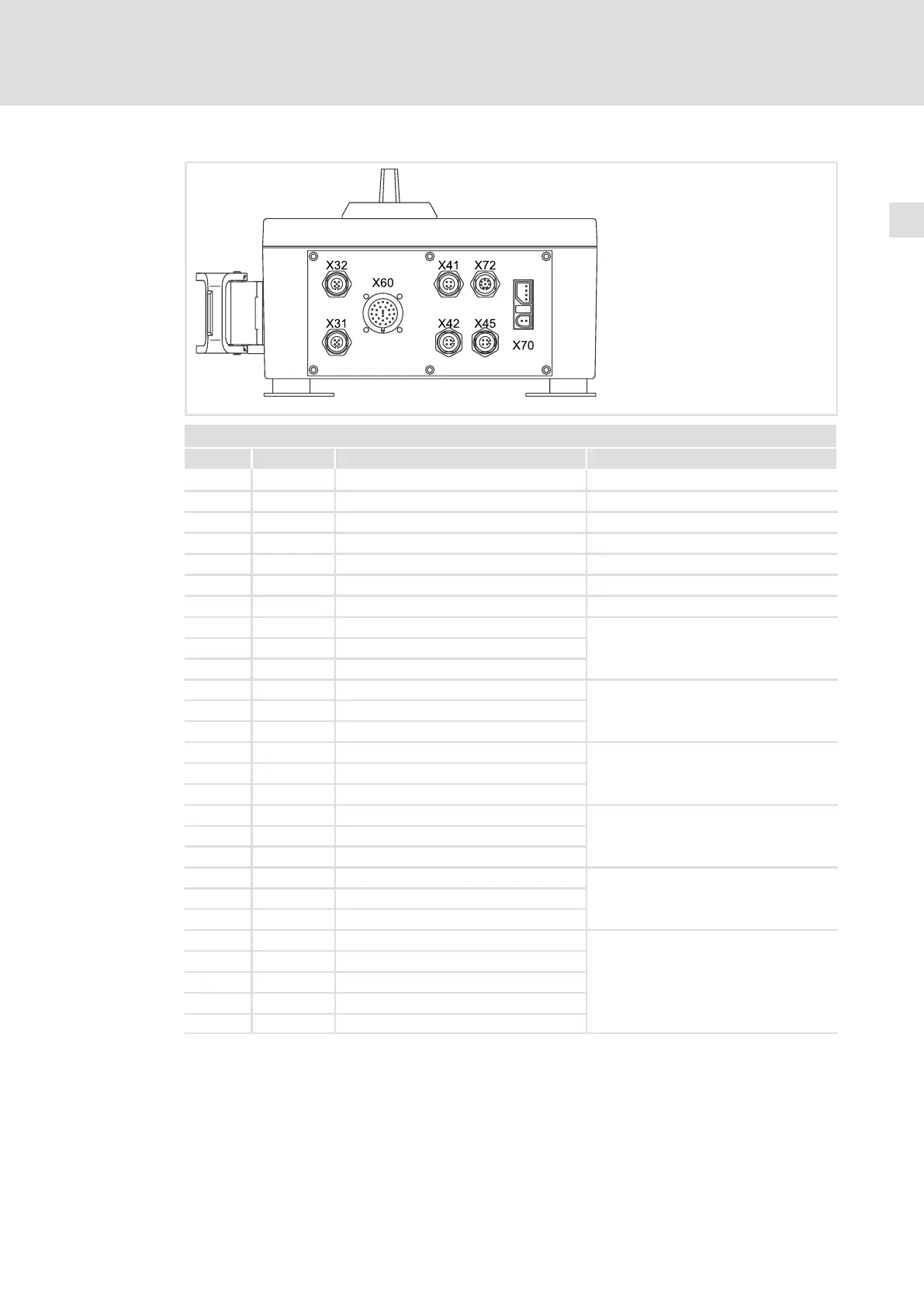
X60 − Safe inputs, safe outputs
Pin Signal Description Data
Connector: Socket, 26−pin, M27, N−coded
1 O1A Output 1 channel A
2 O1B Output 1 channel B
3 GO Reference potential for O1A and O1B
4 O2A Output 2 channel A
5 O2B Output 2 channel B
6 GO Reference potential for O2A and O2B
7 CLB Clock output, channel B
only for passive sensors
8 CLA Clock output, channel A
9 GCL Reference potential for CLA and CLB
10 I1A Sensor input 1, channel A
only for equivalently switching passive
sensors
11 I1B Sensor input 1, channel B
12 GI1 Reference potential for I1A and I1B
13 I2A Sensor input 2, channel A
only for equivalently switching passive
sensors
14 I2B Sensor input 2, channel B
15 GI2 Reference potential for I2A and I2B
16 I3A Sensor input 3, channel A
only for active sensors
17 I3B Sensor input 3, channel B
18 GI3 Reference potential for I3A and I3B
19 I4A Sensor input 4, channel A
only for active sensors
20 I4B Sensor input 4, channel B
21 GI4 Reference potential for I4A and I4B
22 n. c. Not assigned
23 n. c. Not assigned
24 n. c. Not assigned
25 n. c. Not assigned
26 n. c. Not assigned