Electrical installation
Control connections
4
l
64
EDKLCMZ3024−SPS DE/EN 4.0
Digital outputs
) Note!
If inductive loads are being connected, it is essential to use a spark suppressor
at the digital output.
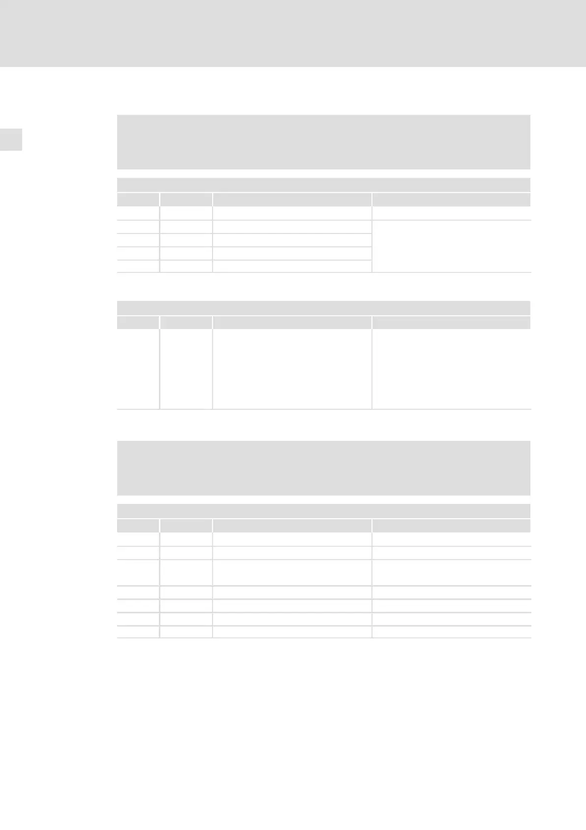
X45 − digital outputs A1, A2
Pin Signal Description Data
Connector: socket, 4−pole, M12
1 +24 V Supply
2 Signal 1 a1 HIGH U
DC
at X11
3
GND Reference potential LOW 0 ... +4 V
4
Signal 2 A2 Max. 500 mA
Diagnostic interface
X70 − Diagnostic interface
Pin Signal Description Data
1 ... 4 Connection for handheld keypad or PC
interface
Connector: Plug connector, 4−pin
Connection only possible using a Lenze
system cable E82ZWLxxx
Only use PC interfaces featuring electrical
isolation:
LECOM−A (RS232) EMF2102IBCV004 or
LECOM A/B (RS232/RS485)
EMF2102IBCV001
Automatic / manual operation
) Note!
Manual operation is only possible if the motor starter is enabled by the safety
PLC!
X72
1)
− Manual operation
Pin Signal Description Data
Connector: Socket, 8−pin, M12
1 +24 V Supply (switch in manual operation)
2 Signal 1 Input automatic/manual operation
HIGH Manual operation
LOW Automatic operation
3 GND Reference potential
4 HI1 Input 1 HIGH CW rotation
5 HI2 Input 2 HIGH CCW rotation
6 ... 8 Reserved
1)
Designation in production lot with hardware version PB: X20