Motor connecon
Connecon via terminal box
Observe the notes on wiring, data on the nameplate, and the connecon diagram in the
terminal box.
The connecon must ensure a connuous and safe electrical supply:
•
No protruding wire ends
•
Use assigned cable end ngs
•
Ensure good electrical conducvity of the contact (remove paint residues) if an addional
PE connecon is used
•
Establish a safe protecve earth connecon
•
Aer the connecon is completed, make sure that all connecons on the terminal board
are rmly ghtened
•
The terminal box has to be free of foreign bodies, dirt, and humidity
•
All unused cable entries and the terminal box itself must be sealed so that they are dust-
ght and waterproof
The smallest air gaps between uncoated, live parts and against earth must not fall below the
following values:
Minimum requirements for basic insulaon
according to IEC/EN 60664-1 (CE)
Higher requirements for UL design Motor diameter
3.87 mm 6.4 mm <178 mm
9.5 mm > 178 mm
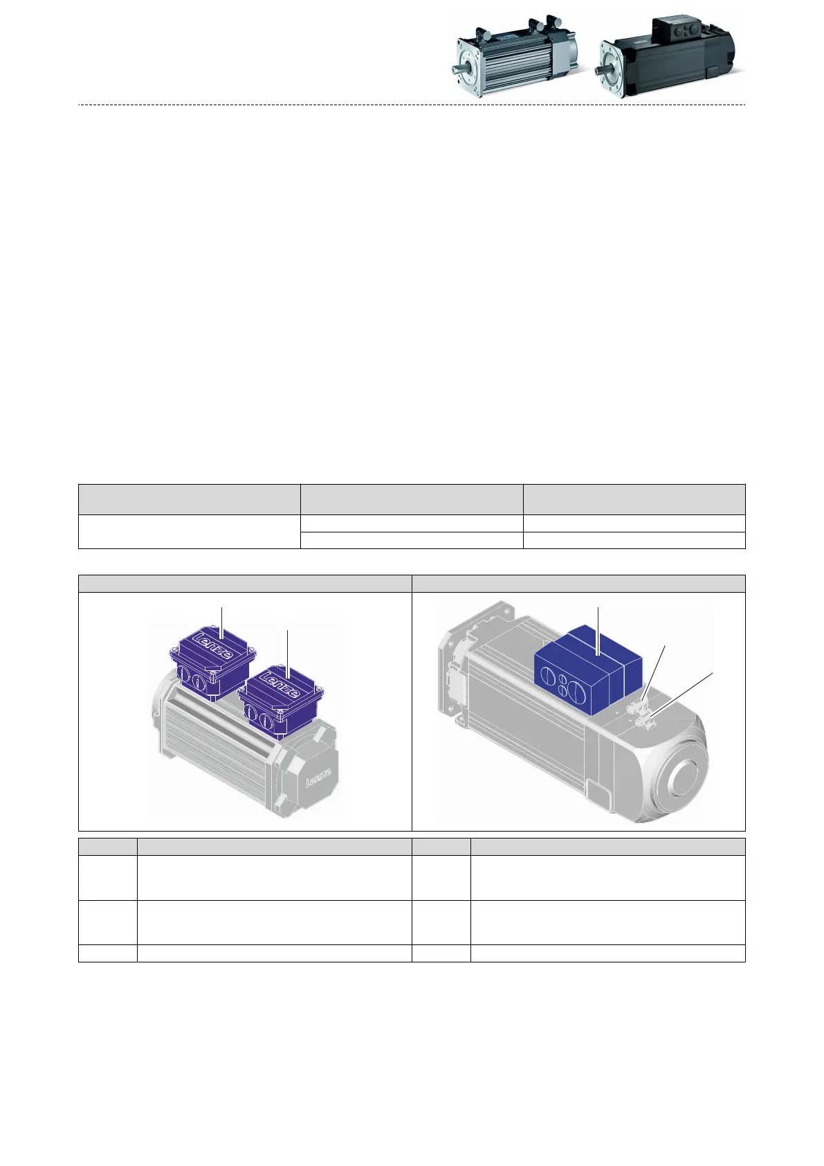
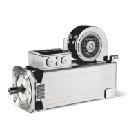
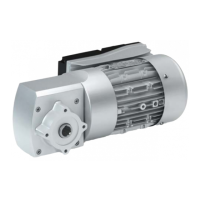
Posion of the connecons
MCA10 ... 19/21 MCA20/22/26
Posion Meaning Posion Meaning
1 Power connecon
Brake connecon
PE connecon
1 Power connecon
Brake connecon
PE connecon
2 Feedback connecon
Connecon of temperature monitoring
Blower connecon
2 Feedback connecon
Connecon of temperature monitoring
3 Blower connecon
Electrical installaon
Motor connecon
Connecon via terminal box
58