Maintenance/repair
Maintenance operations
Spring−operated brakes
8
42
Lenze ¯ BA 33.0005 ¯ 5.0
Wear on spring−applied brakes
The used spring−applied brakes have a low rate of wear and are designed for long
maintenance intervals.
However, the friction lining, the teeth between the brake rotor and the hub, and also the
braking mechanism are naturally subject to function−related wear which depends on
the application case (see table). In order to ensure safe and problem−free operation, the
brake must therefore be checked and maintained regularly and, if necessary, replaced
(see brake maintenance and inspection).
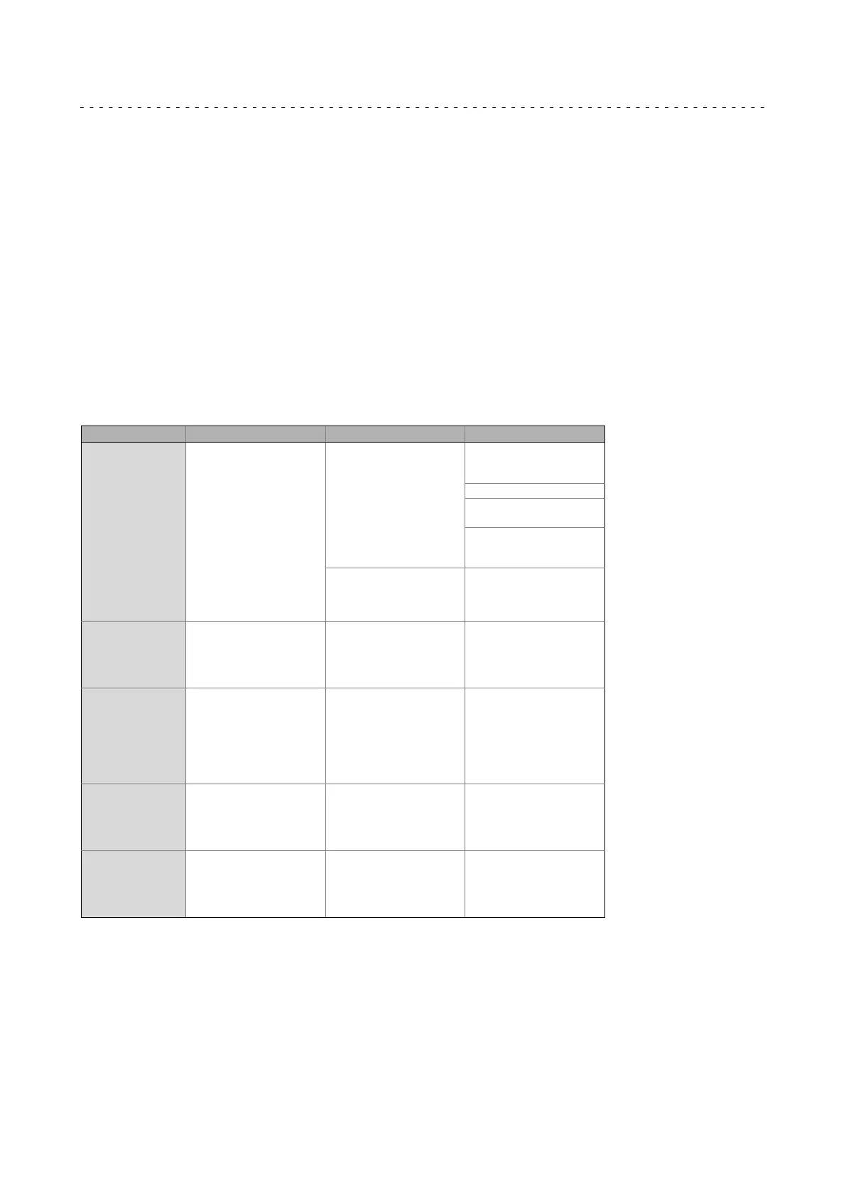
The following table describes the different causes of wear and their effect on the
components of the spring−applied brake. In order to calculate the useful life of the rotor
and brake and determine the maintenance intervals to be prescribed, the relevant
influencing factors must be quantified. The most important factors are the applied
friction energy, the starting speed of braking and the switching frequency. If several of
the indicated causes of wear on the friction lining occur in an application, their effects
are to be added together.
Component Effect Influencing factors Cause
Friction lining Wear on the friction lining Applied friction energy
Braking during operation
(impermissible, holding
brakes!)
Emergency stops
Overlapping wear when
the drive starts and stops
Active braking by the drive
motor with the help of the
brake (quick stop)
Number of start−stop
cycles
Starting wear if motor is
mounted in a position
with the shaft vertical,
even if the brake is open
Armature plate and
flange
Running−in of armature
plate and flange
Applied friction energy Friction between the brake
lining and the armature
plate or flange e.g. during
emergency braking or
service brake operation
Teeth of the brake
rotor
Teeth wear (primarily at
the rotor end)
Number of start−stop
cycles,
Level of the braking
torque,
Dynamics of the
application,
Speed fins in operation
Relative movement and
impacts between brake
rotor and brake hub
Armature plate
bracket
Armature plate, cap screws
and bolts are deflected
Number of start−stop
cycles,
Level of braking torque
Load changes and impacts
due to reversal error
during interaction
between armature plate,
cap screws and guide bolts
Springs Fatigue failure of the
springs
Number of switching
operations of the brake
Axial load cycle and
shearing stress on the
springs due to radial
reversing error of the
armature plate
Tab. 2 Causes for wear
 Loading...