Electrical installation
Screwed connections on the terminal box
Brake connection to terminal
6
31
Lenze ¯ BA 33.0005 ¯ 5.0
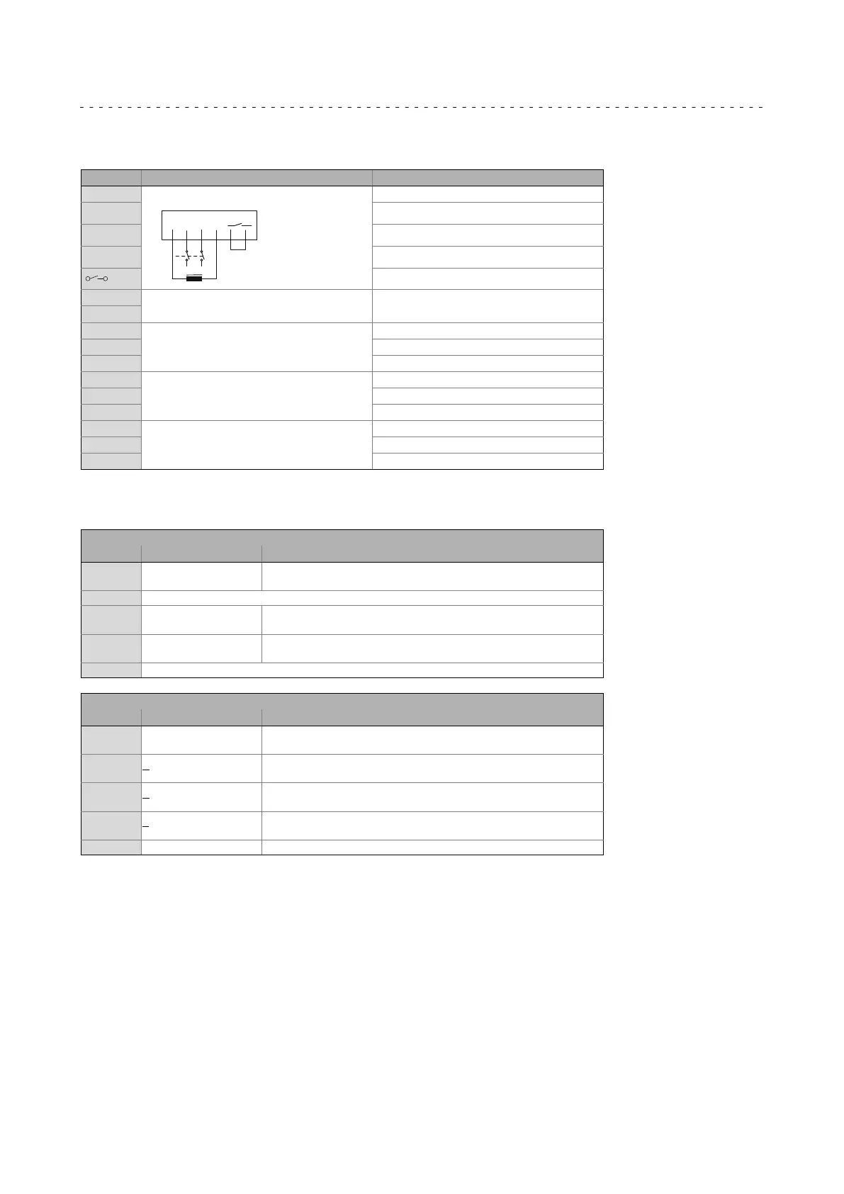
6.4.2 Brake connection to terminal
Contact Meaning Additional specifications
~ AC−excited brake (rectifier) Connection to L1 − mains
~
1
2
3
4
5
6
-
~
~
+
Connection to N − mains
+ Brake connection
− Brake connection
Switching contact, DC switching
BD1 Brake, DC operated DC connection
BD2
MS1 Brake microswitch, release control Two−way switch
MS2 NC contact
MS4 NO contact
MS1 Brake microswitch, wear control Two−way switch
MS2 NC contact
MS4 NO contact
MS1 Brake microswitch, manual release Two−way switch
MS2 NC contact
MS4 NO contact
6.4.3 Feedback system to terminal
Resolver
Contact Name Meaning
B1
B2
+ Ref
− Ref
Transformer windings
(reference windings)
B3 Not assigned
B4
B5
+COS
−COS
Stator winding cosine
B6
B7
+SIN
−SIN
Stator winding sine
B8 Not assigned
Incremental encoder / sin/cos absolute value encoder with Hiperface
Contact Designation Meaning
B1
B2
+ U
B
GND
Supply +
Mass
B3
B4
A / + COS
A
/ Ref cos
Track A / process data channel
Track A inverse / process data channel
B5
B6
B / − SIN
B
/ Ref sin
Track B / process data channel
Track B inverse / process data channel
B7
B8
Z / data +
Z
/ data −
Zero track / parameter channel + RS485
Zero track inverse / parameter channel − RS485
B10
1)
Shield − housing Shield − incremental encoder
1) The terminal is not assigned if insulation at N−end shield of the motor has been selected!
 Loading...