Safety engineering
Device modules
Safety module SM100
1
15
EDS94AYAB EN 2.1
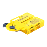
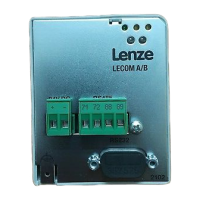
1.2.4.3 Elements of the module
SSP94SM112
Fig. 1−3 Module view
Displays
Pos. Colour Condition Description
EN Yellow
On Controller enabled
Off Non−safe display "Safe pulse inhibit"
DE Red On
The module is not accepted by the standard device (see notes
given in the documentation for the standard device).
Tab. 1−1 LED display SM 100
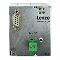
1.2.4.4 Technical data
24 V
The inputs and outputs are isolated and designed for a low−voltage supply through a safely
separated power supply unit (SELV/PELV) of 24 V DC. P/N switching input signals and test
pulses £ 1 ms are permissible.
Output signals of active sensors are directly wired to the X80 terminal.
Passive Sensors are wired to the X80 terminal via a switching device. The switching device
must comply with the required control category of the application.
There is no monitoring for short circuits.
Buy: www.ValinOnline.com | Phone 844-385-3099 | Email: CustomerService@valin.com