EasyManua.ls Logo

Lenze SMD - User Manual

Lenze SMD
36 pages
Print Icon
To Next Page IconTo Next Page
Loading...
SMD
Frequency Inverter: Basic I/O
with CANopen 0.25kW... 4.0kW
Operating Instructions
(13466185)

Questions and Answers

  • R
    rachel92Aug 31, 2025
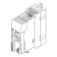
    What causes undervoltage on DC bus in Lenze Inverter?
    • T
      Trevor BlackAug 31, 2025
      If the Lenze Inverter shows 'Undervoltage on DC bus', the mains voltage might be too low. Check the mains voltage to ensure it is within the required range.
  • C
    Christopher MitchellAug 25, 2025
    What causes overvoltage on DC bus in Lenze SMD DC Drives?
    • M
      Melissa HarrisAug 25, 2025
      If you see 'Overvoltage on DC bus' on your Lenze DC Drive, it could be due to the mains voltage being too high, so you should check the mains voltage. It could also be caused by an excessively short deceleration time or the motor operating in generator mode. To resolve this, increase the deceleration time or use a dynamic braking option. Another cause could be earth leakage on the motor side, so check the motor/motor cable, separating the motor from the controller.
  • C
    coopermatthewAug 25, 2025
    What causes motor overload in Lenze SMD DC Drives?
    • T
      Thomas VargasAug 26, 2025
      If your Lenze DC Drive reports 'Motor overload (I2t overload)', the motor may be thermally overloaded due to impermissible continuous current or frequent/long acceleration processes. Check the controller selection and the setting of c20.
  • A
    Andrea GomezAug 26, 2025
    How to fix stop error on Lenze SMD?
    • K
      Kimberly MartinezAug 26, 2025
      If the Lenze DC Drive displays 'Stop (outputs U, V, W inhibited)', it indicates a LOW signal at terminal 28. Set terminal 28 to HIGH to resolve this.
  • C
    courtneyjohnsonAug 26, 2025
    What does external error mean on Lenze DC Drives?
    • F
      fbryantAug 26, 2025
      If your Lenze DC Drive reports 'External error', it means the digital input “TRIP set” is active. You should remove the external error to resolve this.
  • D
    Douglas McdonaldAug 27, 2025
    What causes faulty auto-TRIP reset on Lenze SMD DC Drives?
    • T
      Timothy BaileyAug 27, 2025
      If your Lenze DC Drive displays 'Faulty auto-TRIP reset', it means there have been more than 8 errors in 10 minutes. The solution depends on the specific error.
  • H
    Heather JohnsAug 27, 2025
    What to do if Lenze SMD have overvoltage on DC bus?
    • Z
      Zachary GibsonAug 27, 2025
      Overvoltage on the DC bus in Lenze DC Drives may be due to several reasons. It can be caused by mains voltage being too high (check mains voltage), an excessively short deceleration time or the motor operating in generator mode (increase deceleration time or use dynamic braking option), or earth leakage on the motor side (check motor/motor cable, separating the motor from the controller).
  • A
    Austin LaneAug 27, 2025
    What causes Lenze SMD DC Drives to have earth fault?
    • O
      ocurryAug 27, 2025
      An earth fault in Lenze DC Drives may be caused by a grounded motor phase (check motor/motor cable) or excessive capacitive charging current of the motor cable (use shorter motor cables).
  • J
    james34Aug 28, 2025
    What to do if Lenze DC Drives show external error?
    • S
      stephen83Aug 28, 2025
      If your Lenze DC Drive shows an external error, it means the digital input “TRIP set” is active. Remove the external error to resolve this.
  • T
    thomaslaurenAug 28, 2025
    What causes single phase fault in Lenze DC Drives?
    • D
      David FernandezAug 28, 2025
      If your Lenze DC Drive is showing a single phase fault, it means a mains phase has been lost. Check the mains voltage.

Summary

About These Instructions

Scope of Delivery

Details items included with the inverter.

Important Notes

Critical information regarding product receipt and checks.

Safety Information

General Safety Precautions

Overall safety guidelines for handling and operation.

Application as Directed

Specifies intended use and compliance with directives.

Installation Safety

Guidelines for safe mechanical and electrical installation.

Operation Safety

Safety considerations during the operation of the inverter.

Pictographs and Warnings

Explains symbols and signal words used in the manual.

Technical Data

Standards and Application Conditions

Lists relevant standards and environmental operating conditions.

Product Ratings

Details electrical specifications and output current ratings.

Installation

Mechanical Installation

Covers physical mounting and dimensions of the inverter.

Electrical Installation

Details wiring, EMC requirements, and connection diagrams.

Commissioning

Parameter Setting Overview

Explains how to set and adjust operating parameters.

Electronic Programming Module (EPM)

Describes the EPM for storing and managing parameter settings.

Parameter Menu Structure

Details the codes, names, and functions of various parameters.

CANopen Mapping Details

Defines how data is mapped for CANopen communication.

RPDO Mapping Details

Specifies the mapping of Receive PDO data.

TPDO Mapping Details

Specifies the mapping of Transmit PDO data.

Quick CAN Setup

Guides through the initial setup for CAN communication between controllers.

Troubleshooting and Fault Elimination

Status Indicators and Basic Faults

Explains status codes and common basic operational faults.

Specific Error Codes and Causes

Lists specific error codes, their causes, and remedies.

CAN Communication Faults

Addresses faults related to CAN communication timeouts and initialization.

Circuit and Overload Faults

Covers faults related to short circuits, overloads, and voltage issues.

Lenze SMD Specifications

General IconGeneral
Product seriesSMD
CategoryDC Drives
Field currentUp to 2 A
Control modeSpeed, torque, position
ProtectionOvercurrent, overvoltage, overtemperature

Related product manuals