KRTM 3B… - 08 2016/11
Specifications
Optical data
Scanning range
1)
1) Scanning range: recommended range with performance reserve
14.5mm ± 2mm
Light spot dimensions in RUN-Mode
in Teach-Mode
1.5mm x 4mm (at a distance of 14.5mm)
1.5mm x 6.5mm (at a distance of 14.5mm)
Light spot orientation vertical or horizontal (see dimensioned drawing)
Light source
2)
2) Average life expectancy 100,000h at an ambient temperature of 25°C
LEDs (red, green, blue)
Wavelength 640nm, 525nm, 470nm
Sensor operating modes
IO-Link COM2 (38.4kBaud)
SIO standard push-pull
Timing of the sensor
Internal switching frequency 10kHz
Internal response time 50μs
Response jitter, internal 20μs
Repeatability
3)
3) At conveyor speed 1m/s
0.02mm
Delay before start-up ≤ 300ms
Conveyor speed during teach ≤ 0.1m/s for a mark width of 1mm
Teach process static 1-point, static 2-point or dynamic 2-point
Teach delay ≤ 10ms
Timing of the outputs
Response time SIO operation (without IO-Link): 50μs
COM2 (with IO-Link): typ. 2.5ms
Electrical data
Operating voltage U
B
4)
with SIO
with COM2
4) For UL applications: for use in class 2 circuits according to NEC only
10 … 30VDC (incl. residual ripple)
18 … 30VDC (incl. residual ripple)
Residual ripple ≤ 15% of U
B
Output/function …/2…
…/4…
…/6.0001…
…/6.1121…
…/L6.1121…
pin 4: NPN transistor, GND if mark detected
pin 4: PNP transistor, U
B
if mark detected
pin 4: push-pull switching output,
PNP: U
B
if mark detected
, NPN: GND
if mark detected
pin 4: IO-Link 1.0
pin 4: IO-Link 1.1
Signal voltage high/low ≥ (U
B
-2V)/≤ 2V
Output current max. 100mA
Open-circuit current ≤ 25mA
Indicators
Green LED in continuous light ready
Green and yellow LED flashing at 3Hz teach event active
Green and yellow LED flashing at 8Hz teaching error
Green LED off and yellow LED flashing at 8Hz
sensor error
Yellow LED in continuous light mark detected (dependent on the teach sequence)
Transmitter LEDs flashing at 8Hz teaching error
Mechanical data
Housing plastic (PC-ABS), with nickel-plated mounting sleeve
Optics cover plastic (PMMA)
Weight 10g
Connection type M8 connector, metal
Environmental data
Ambient temp. (operation/storage) -30°C … +55°C/-30°C … +70°C
Protective circuit
5)
5) 2=polarity reversal protection, 3=short-circuit protection for all transistor outputs
2, 3
VDE safety class III
Protection class IP 67
Light source
free group (in acc. with EN 62471)
Standards applied IEC 60947-5-2
Certifications UL 508, C22.2 No.14-13
4)
6)
6) These proximity switches shall be used with UL Listed Cable assemblies rated 30V, 0.5A min,
in the field installation, or equivalent (categories: CYJV/CYJV7 or PVVA/PVVA7)
Options
Input pin 2 (not for KRTM 3B/L6…)
Function characteristics keyboard lockout / line teach / pulse stretching
Input active/not active ≥ 8V/≤ 2V or not connected
Output pin 4
Line teach active for SIO
for COM2
2Hz at the switching output
see configuration file IODD
Error after line teach for SIO
for COM2
2Hz at the switching output
see configuration file IODD
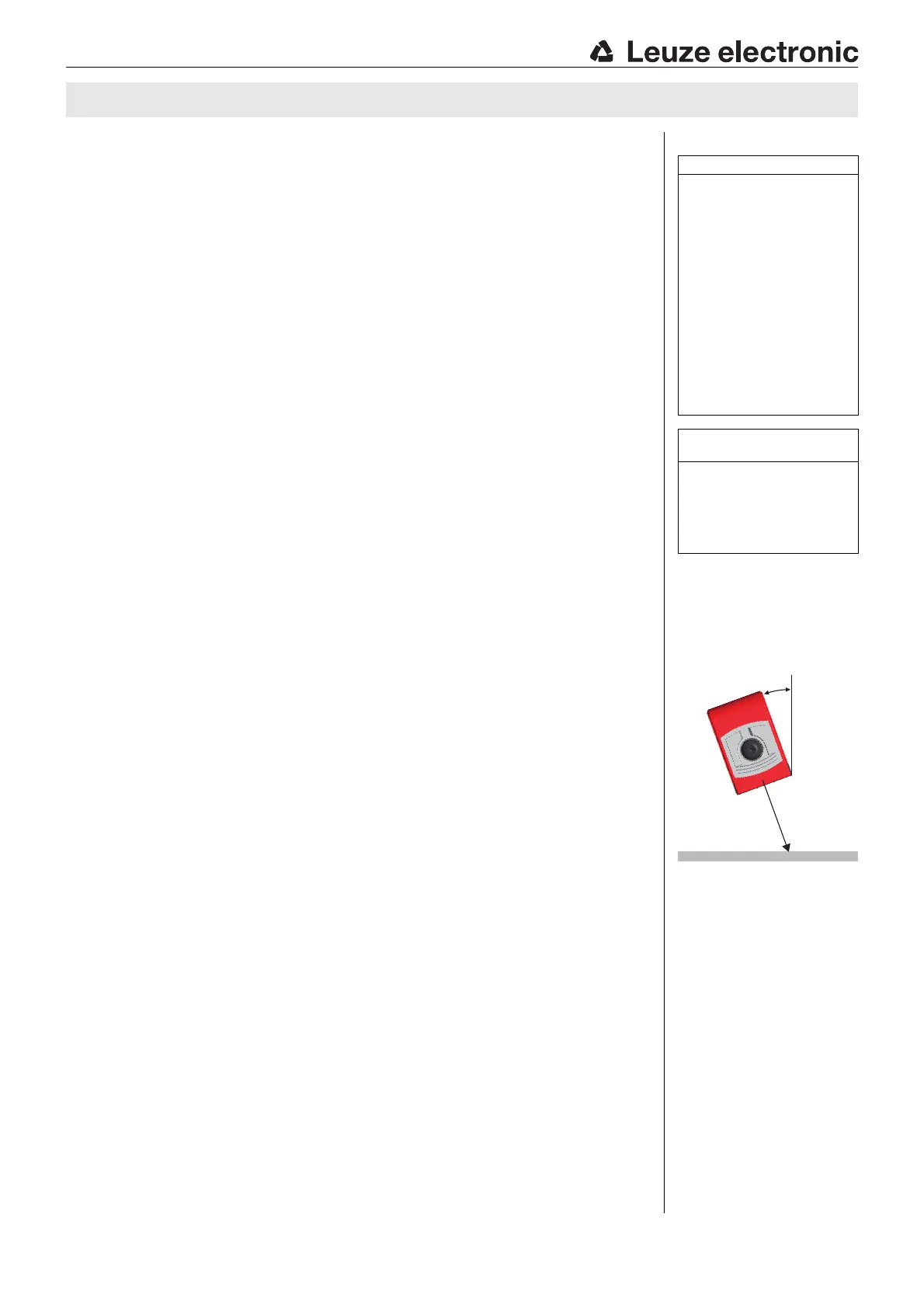
Remarks
With glossy objects, the
sensor is to be fastened at
an inclination of
approx. 10° relative to the
object surface.
UL REQUIREMENTS
Enclosure Type Rating: Type 1
For Use in NFPA 79 Applications
only.
Adapters providing field wiring
means are available from the manuf-
acturer. Refer to manufacturers in-
formation.
CAUTION – the use of controls or
adjustments or performance of
procedures other than those spe-
cified herein may result in hazar-
dous radiation exposure.
ATTENTION ! Si d'autres disposi-
tifs d'alignement que ceux préco-
nisés ici sont utilisés ou s'il est
procédé autrement qu'indiqué,
cela peut entraîner une exposition
à des rayonnements et un danger
pour les personnes.
Operate in accordance with
intended use!
This product is not a safety sensor
and is not intended as personnel
protection.
The product may only be put into
operation by competent persons.
Only use the product in accor-
dance with the intended use.
KRTM 3B
 Loading...