Terminal block for I/O connectors
Four sets of Digital Input, DI1 until DI4; the internal device is also
photo-coupled electrical relay. In practice, the external device can be
simply an On/Off switch. Four sets of On/Off switch can be connected as
different trigger source.
Digital output implementation; Pin6 to COM (Pin7) is a Photo-coupled
relay on Normal Open status. External device can directly connect to the
terminals. However the current that will go through the 2 nodes must not
exceed 130mA. An external “Relay” can also be connected to the
terminals as an implementation. In this case, current (or/and voltage)
limitation is specified by the external Relay.
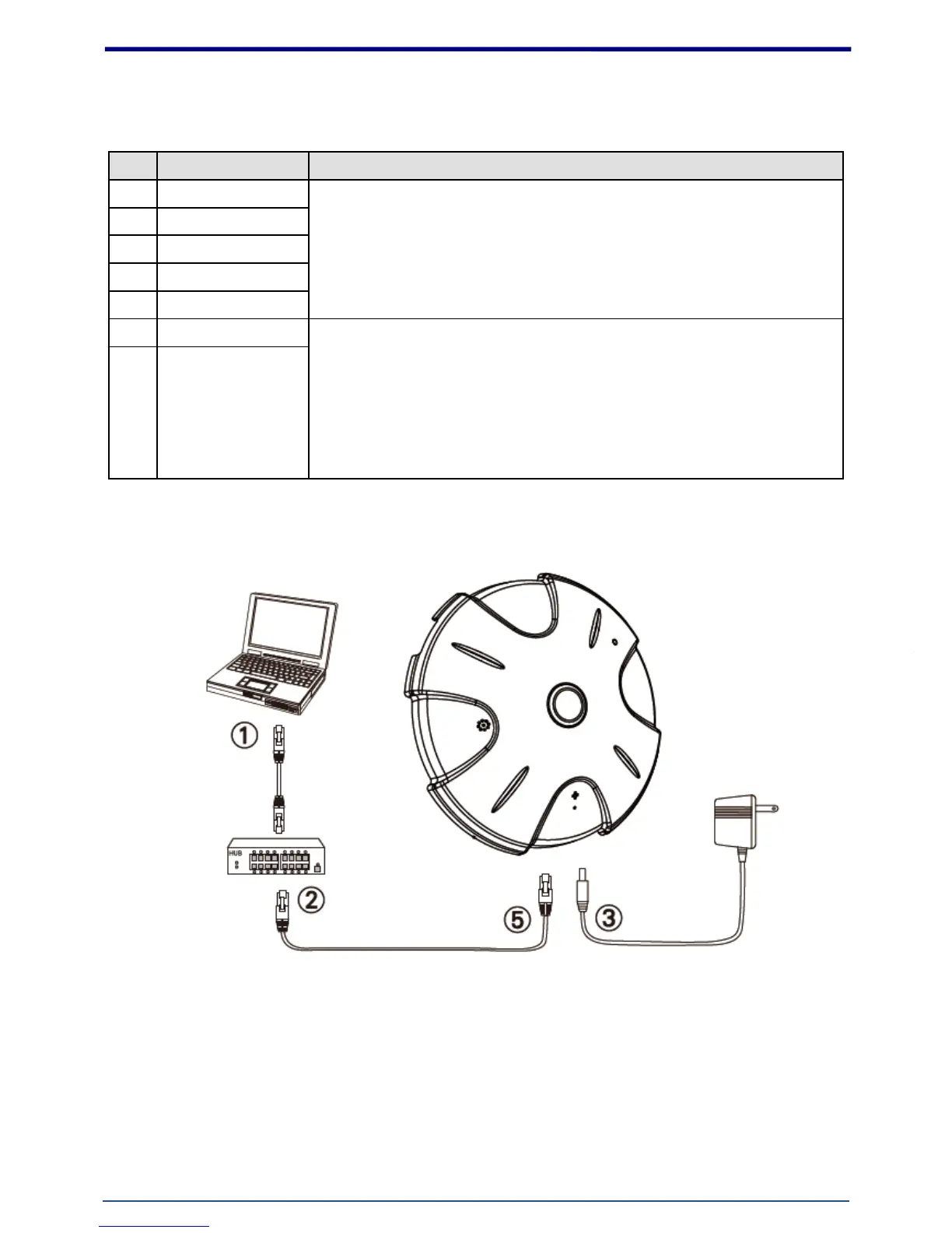
1. Hardware Connection
1. Prepare a PC with Ethernet link to the network
2. Connect LAN port (RJ45) of the camera to a network switch/hub
3. Connect power jack
4. Ensure the power adaptor specification matches the power system (110V or 220V) and connect
the adaptor to the outlet
5. Check LED status (Power/Network)