Series 2000 MMU Installation Manual
Leviton Manufacturing Co., Inc. 13 3.0 Installation Instructions
3. Attach the conduit between enclosure and load center, routing wires as
necessary for later use.
4. Make sure the conduit fittings are aligned properly and tightened securely to
prevent moisture from entering the enclosure.
3.6 Installation of Voltage Lines
Note: A panel schedule is highly recommended for factory pre-wiring of MMU internal
voltage connections.
1. Verify that branch circuit fuse specifications meet local electric codes.
2. Connect 18 AWG min., 600 V min. insulated wiring for Line voltages and Neutral
to the appropriate locations in the breaker panel, in accordance with all national and
local electrical codes.
3. Route wires through the conduit if not already done.
4. Trim the wire to the appropriate length to avoid coils of excess wiring.
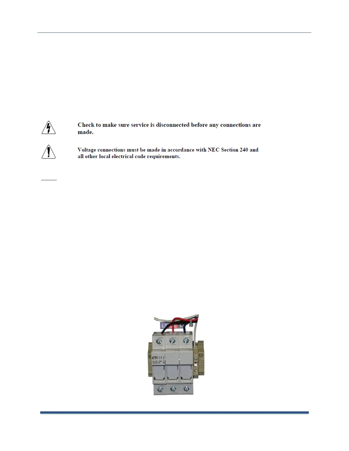
5. For connections to voltage terminal fuse block in MMU (see below), strip wiring to
approximately .300 inches if needed and connect to the appropriate terminals. Wires
should be tightened so that they are held snuggly in place, but do not to over-tighten,
as this may compress and weaken the conductor.
 Loading...