40
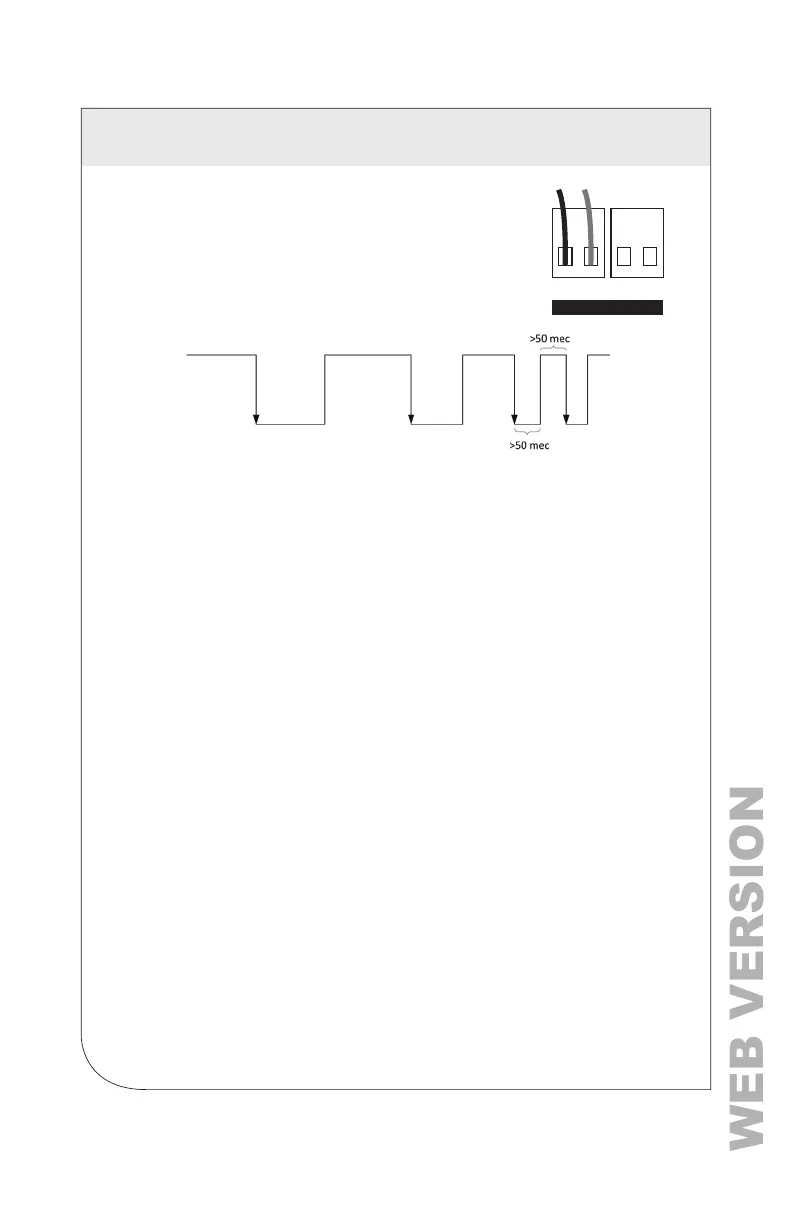
6.7 Pulse Inputs
Series 7000 and 7100 meters are equipped with 2 pulse
inputs. Pulse counting supports the accumulation of
consumption data from any external meter using a dry contact
(Form A Relay) or open collector outputs. The pulse inputs are
compatible with “low-speed” meters. The pulse duration must
exceed 50 mS in both the logic low- and high-states, which all
a maximum input frequency of 10 Hz.
Pulse scaling, resetting, and accumulated values are accessed through registers,
and are “system” in scope.
Refer to the register list or Power Meter Viewer Utilities software for more information.
6.8 Alarms (SPDT)
The VerifEye
®
meter supports user-congurable alarms for over-current,
under-current, over-voltage, and under-voltage. Use the Power Meter Viewer
Utilities software to enter values by using the direct entry mode, or specifying the
limits as a percentage of nominal.
Alarm persistence settings allow for temporary conditions, such as a motor starting,
that are beyond trigger limits.
EXAMPLE: If a meter upset from ESD event occurs, short persistence settings
may lead to false alarm triggers. When any alarm condition has been satised
throughout the persistence interval, the meter trips the Master Alarm relay, which is
an electromechanical relay on the PCB.
Once tripped, the relay can only be reset by clearing the alarm through Modbus
register/BACnet object 2451.
The Master Alarm relay can be hard wired to an interrupt or polling circuit in a host
system, which allows a faster response than the data polling frequency. The status
of each alarm is determined by reading status registers.
Refer to the register list or Power Meter Viewer Utilities software for more information.
NOTE: The Master Alarm relay is intended for low-voltage DC connections. The
user must protect the switch from over-current conditions when closed.
6.9 12 Volt Auxillary Power
The VerifEye
®
meter provides an auxiliary 12 volt output that is derived from an
auxiliary winding on the VerifEye
®
meter’s line-connected power supply. The 12 volt
supply voltage is unregulated, but protected by a self-resetting fuse. The purpose
of the supply is to power external radio equipment, or provide supply voltage for
analog sensors, such as 4-20 mA current loop devices. If full-rated current is drawn
from this terminal, the minimum operating voltage of the L1-L2 power supply is
100V AC.
PULSE INPUT12
C(+) E(-) C(+) E(-)
6 COMMUNICATION AND VERIFICATION