36
This section describes how to commission the meter by an instrumentation technician.
You can perform the electrical installation prior to the availability of the RTU; however,
the instrumentation technician works with a remote programmer who conrms the
connectivity with a remote host system. You can also use a Digital Multimeter (DMM) to
conrm measurements at the board's terminals, if necessary.
WARNING: It is assumed that the meter is now powered up from the line voltage.
ONLY IF THE INTERNAL HIGH VOLTAGE COVER IS INSTALLED is it safe to touch the
meter (including the user buttons) with the top cover removed.
NOTE: Communications settings and real-time data values can be conrmed quickly
using the LCD interface if equipped. When signicant setup modications are anticipated,
a computer interface is recommended.
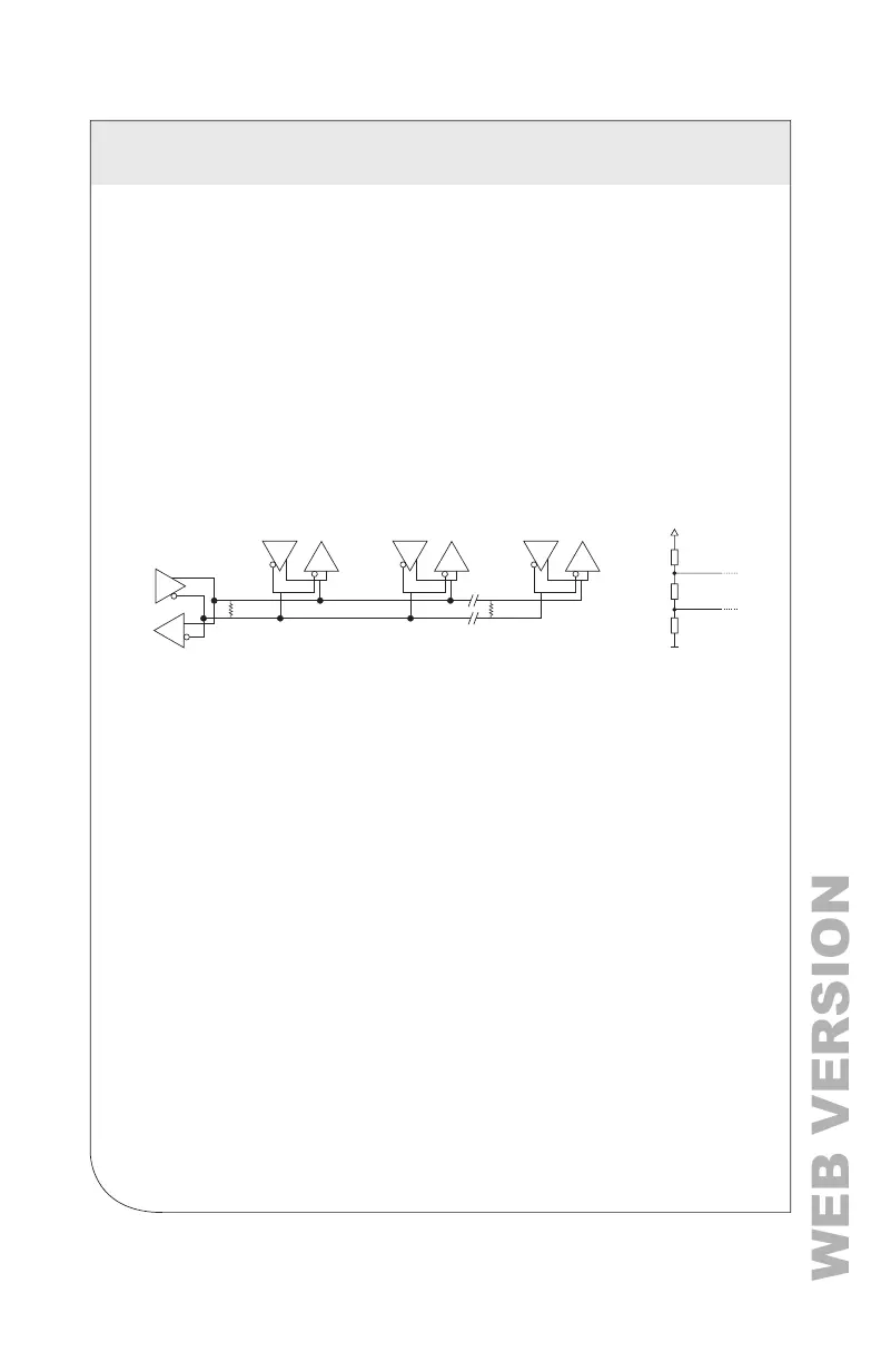
6.1 Physical Connections on an RS-485 Multi-Drop Network
The VerifEye
®
meter uses a 2-Wire, Half-Duplex RS-485 implementation.
• Termination Resistors — These are NOT included on the VerifEye
®
meter. If the
VerEye meter is at the end of a daisy-chain, then connect a 120 ohm-leaded
resistor between the + and – terminal at the connector.
• Bias Resistors — These are NOT included on the VerifEye
®
meter. Bias resistors
are needed if the idle conditions of the bus are in an indeterminate logic voltage.
Bias resistors are usually located at the master node and are usually 680 ohms
on an RS-485 network.
• Network Topology — RS-485 is designed to be implemented as a daisy chain
(series of connections) rather than star or cascade topologies.
• Signal Names — Some RS-485 devices use the terminology A/B while others
use +/-. Note that A is (-) and B is (+).
• Bus Loading — The VerifEye® meter is 1/8 of a unit load that allows you to
connect up to 256 like devices in parallel.
MASTER
Slave 1
120 ї
Slave 2
Tx
Tx
Rx
Rx
Tx
Rx
Slave n
Tx
Rx
120 ї
680ї
+
-
120ї
680ї
6 COMMUNICATION AND VERIFICATION