37
6.2 Communication Verication
Verication includes conrmation of BOTH the physical interface settings (Serial or
Ethernet) and the protocol (Modbus or BACnet) settings.
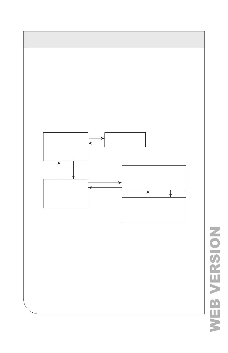
Use the LCD's user's interface to quickly conrm the settings required for each
combination of interface settings and protocol. The interface is intuitive and groups
together commonly associated registers. Arrows indicate how to move from one
menu to the next. The active menu item is indicated by a blinking character on the
LCD. Press the ENTER button to select a value, and up/down buttons to select the
values supported by the meter.
NOTE: Changes to the meter conguration are limited to the communication
interface using the LCD. If additional changes, such as CT type, are required, they
must be made using a software interface.
Power Meter Viewer Utilities and VerifEye
®
Web App
If your VerifEye
®
model does not include the LCD user interface, or if you prefer
to verify the installation with software, use the Power Meter Viewer Utilities PC
application or the VerifEye
®
Web App, which shares a common design, to verify
communications. Refer to the Conguration Details section for an overview and list
of instructional videos for Power Meter Viewer Utilities or the VerifEye
®
Web App.
NOTE: A full navigational map is available in Appendix A.
View Communications
Real Time Values
View Meter Setup
Verify Installation
Log In/Out
About Meter
View Communications
Real Time Values
View Meter Setup
Verify Installation
Log In/Out
About Meter
Protocol: BACnet
Baud Rate: 9600
Bits: 8N1
View Communications
Real Time Values
Main Menu
Element A Channels
V
A
kW
100
23.2
2.0
101
22.9
2.0
99.9
22.0
2.0
Element A Channels
kVA
kVAR
kWH
100
100
1234
110
-110
***
111
123
100
6 COMMUNICATION AND VERIFICATION