Page 2
INSTALLATION
Go over your plan with your customer.
1. Install the entire system. Refer to sections in this manual to see how to install various components.
2. Follow the Power-Up and Checkout procedures.
3. Explain the basics to the customer. Deliver all manuals and documentation.
4. Follow up with your customer to keep them satisfied.
CONTROLLER HOOKUP
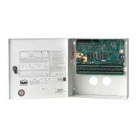
1. When choosing a place to mount the controller, consider the following:
a. A duplex outlet, preferably on its own circuit, is required to be within 5 feet of the controller for the power transformer and
the UPB PIM or X-10 Interface Module.
b. The controller should be protected from weather, temperature extremes, and burglars.
2. GROUND THE CONTROLLER "EARTH GND" TERMINAL TO A COLD WATER PIPE OR TO A 4-FOOT GROUND
ROD TO PRESERVE ITS BUILT-IN TRANSIENT PROTECTION. USE 14 GAUGE WIRE. TRANSIENT
PROTECTION WILL NOT WORK IF THE CONTROLLER IS NOT PROPERLY GROUNDED.
3. Connect the 24 VAC power transformer to the 24 VAC INPUT terminals.
4. Connect the BLACK battery wire to the minus (-) terminal on the battery. DO NOT connect the red wire at this time. DO
NOT reverse the connections; the battery fuse will blow. Note that the unit will NOT START on the battery alone.
5. Connect the Powerline Interface Module to the OmniPro II controller:
a) UPB PIM (P/N: 36A00-1): Plug one end of the 6-conductor modular cable into the connector marked “J3” (SERIAL 3)
on the OmniPro II controller and plug the other end into the modular connector on the PIM.
b) X-10 Interface Module (P/N: TW523): Plug one end of the 4-conductor modular cable into the connector marked “J7”
(X-10) on the OmniPro II controller and plug the other end into the modular connector on the X-10 Interface Module.
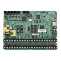
6. Refer to FIGURE 1 (CONTROLLER HOOKUP) for this configuration.


 To Next Page