Home
Leviton
Security System
omnilte
Leviton omnilte User Manual
4
of 1
of 1 rating
75 pages
Give review
Manual
Specs
To Next Page
To Next Page
Loading...
Installation Manual
Control & Security System
Inc
ludes the SIA CP-01 Contr
ol P
anel Standar
d
Features f
or F
alse Alarm Reduction
WEB
VERSION
2
Table of Contents
Installation Manual
1
Table of Contents
4
Introduction
7
Planning
7
Installation
8
Controller Hookup
8
Figure 1 - Controller Hookup
9
About Security Zones
10
Burglar Zone Hookups
10
About Fire Zones
11
Figure 2 - Overall Connections Diagram
11
Four-Wire Smoke Detectors
12
Two-Wire Smoke Detectors
12
Figure 3 - Two-Wire Fire Zone Connections
13
Figure 4 - Four-Wire Fire Zone Connections
14
Telephone Connections
15
Digital Subscriber Line (Dsl) Connections
15
Figure 5 - Rj31X Jack Connections
16
Lcd Console Hookup
17
Figure 6 - Rj31X Jack Connections
17
Console Setup
18
Console Address
18
Sounder
18
Key Click
18
Key Backlight
18
Viewing Adjustment
18
Figure 7 - Console Connections
19
Sounder Outputs
20
Interior Sounder Hookup
20
Exterior Sounder Hookup
20
Figure 8 - Sounder Connections
21
Controller Outputs
22
Reset Outputs
22
Output Applications
22
General Purpose Switching Applications
22
Sounder Triggering
22
Figure 9 - Resetting Controller Outputs
22
Communicator Outputs
23
Armed" and "Ok to Arm
23
Switched Output
23
Omnistat Communicating Thermostats
23
Remote Arm/Disarm Switch
23
Figure 10 - Remote Keyswitch Connections
24
Omnistat Thermostats
25
Figure 11 - Omnistat2 Thermostat Connections
25
Programmable Energy Saver Modules
26
Temperature, Outdoor Temperature, and Humidity
27
Figure 12 - Temperature / Humidity Sensor Connections
27
Figure 13 - Pesm Connections
28
Built-In Serial Ports
29
Figure 14 - Rs-232 Connections
29
Built-In Ethernet Port
30
Controller Ip Address, Port Number, and Encryption Key
30
Figure 15 - Rs-485 Connections
30
Controller Ip Address
31
Controller Port Number
31
Encryption Key
31
Ethernet Connections
31
Connecting to Network Via Pc Access
33
Figure 16 - Local Network
33
Figure 17 - Local / Wide Area Network
34
System Power up Procedure
35
Console Check out
35
Telephone Check out
35
Burglar Zone Check out
36
Fire Zone Check out
36
Customer Checkout
36
In Case of Trouble
37
Consoles
37
Controller
37
Digital Communicator
39
Description of Contact ID
39
Description of 4/2 Format
40
3/1 Format
40
Opening and Closing Reports
40
Installer Setup
41
Setup Control
41
X-10 House Code
41
Upb Network ID
41
X-10 3-Phase
42
UPB Transmit Count
42
Output Types
43
Z-Wave Node ID
44
Setup Zones
44
Wireless Receiver
44
Zone Resistors
44
Zone Response Time
45
Zone Types
45
Latching Zone Types
46
Description of Zone Types
46
Setup Digital Communicator
49
First Phone Number, First Account Number
49
Communicator Type
49
Two-Way Audio
50
Report Open/Close
50
Report Bypass / Restore
50
AC Fail Report Time
50
Automatic Test Time
50
ALARM CODES (4/2 and 3/1 Formats)
51
Setup Temperatures
51
Temperature Display
51
Thermostat Type
51
Z-Wave Thermostat Node ID
52
Setup Miscellaneous
52
Installer Code
52
Enable Pc Access
52
Pc Access Code
53
Call Back Phone Number
53
Outside Siren Delay
53
Dial out Delay
53
Alarm Reset Time
53
Arming Confirmation
54
Fire Alarm Verification
54
Supervise Int Sndr
54
Supervise Ext Sndr
55
Enable Emergency Keys
55
Time Display
55
Date Display
55
Ac Power Frequency
55
Dead Line Detect
55
Off Hook Detect
55
Pickup after Hangup
56
Clock Adjustment
56
Model and Software Version
56
Reset System Eeprom
56
Reset System Ram
56
Ethernet Mac Address
56
Setup Expansion
57
Serial Address
57
Serial 1 Rate
57
Serial 1 Function
57
Serial 2 - Serial 5 Rate
57
Serial 2 - Serial 5 Function
57
LEVITON Access Control
58
Enrolling Access Control Readers
58
Deleting Access Control Readers
58
Unlock Time
59
Exit Time
59
Lock Type
60
Reader Arm/Disarm
60
Setup Zone Options
61
Swinger Shutdown Number
61
Cross Zone Window
61
Zone 1 Options - Zone 32 Options
61
Sia Cp-01 Compliance
62
Minimum Equipment Requirements for a CP-01 Compliant Installation
62
Omni Lte SPECIFICATIONS
63
Underwriter's Laboratories (Ul) Installation Requirements
64
24-Hour Standby Battery Capacity
65
Figure 18 - 24-Hour Standby Connections
65
Smoke Detector Installation Guidelines
66
Appendix A - Contact ID Reporting Format
67
Appendix B - Digital Communicator Code Sheet
68
4
Based on 1 rating
Ask a question
Give review
Questions and Answers:
Need help?
Do you have a question about the Leviton omnilte and is the answer not in the manual?
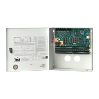
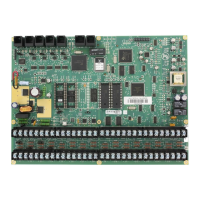
Ask a question
Leviton omnilte Specifications
General
Zones
8
Current Rating
1A
Housing Material
Plastic
Color
White
Operating Temperature
0° to 49° C (32° to 120° F)
Wire Size
18-22 AWG
Related product manuals
Leviton OmniPro II
86 pages
Leviton Omni Pro II
124 pages