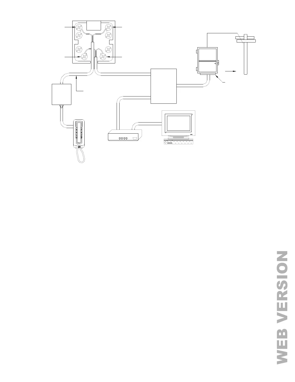
FIGURE 6 - RJ31X JACK CONNECTIONS
LCD CONSOLE HOOKUP
1. 4 LCD Consoles (Models 33A00-1, 33A00-4, 11A00-1, 11A00-2, 11A00-9, and 15A00) MAXIMUM per system,
subject to power availability.
2. Use 4-conductor 22-gage wire, 1000 feet maximum length. Consoles can be homerun or daisy chained. This
length shall be divided by the total number of consoles at the end of the run. For example, for 8 consoles, the
maximum length reduces to 125 feet. All LCD Consoles are connected to the same 4 wires, +12, GND, A, B.
3. The console should be mounted so that the LCD display is at or slightly above eye level. Consoles should be
kept out of the reach of young children. A good height is approximately 58 inches from the floor to the bottom of
the console enclosure.
4. Remove console face from back plate (slots on bottom of console will release back plate, use a screwdriver).
Mount the back plate to the wall. Mounting holes are designed to fit on a single or double gang box, or directly to
the wall. Pull the wires from the wall through the opening in the back plate. Splice the wires to the supplied
cable. Connect the cable to the connector on the console board (J1). Snap the console face on to the back plate.
Remove protective film from the LCD lens.
5. Refer to FIGURE 7 (CONSOLE CONNECTIONS) for this configuration.