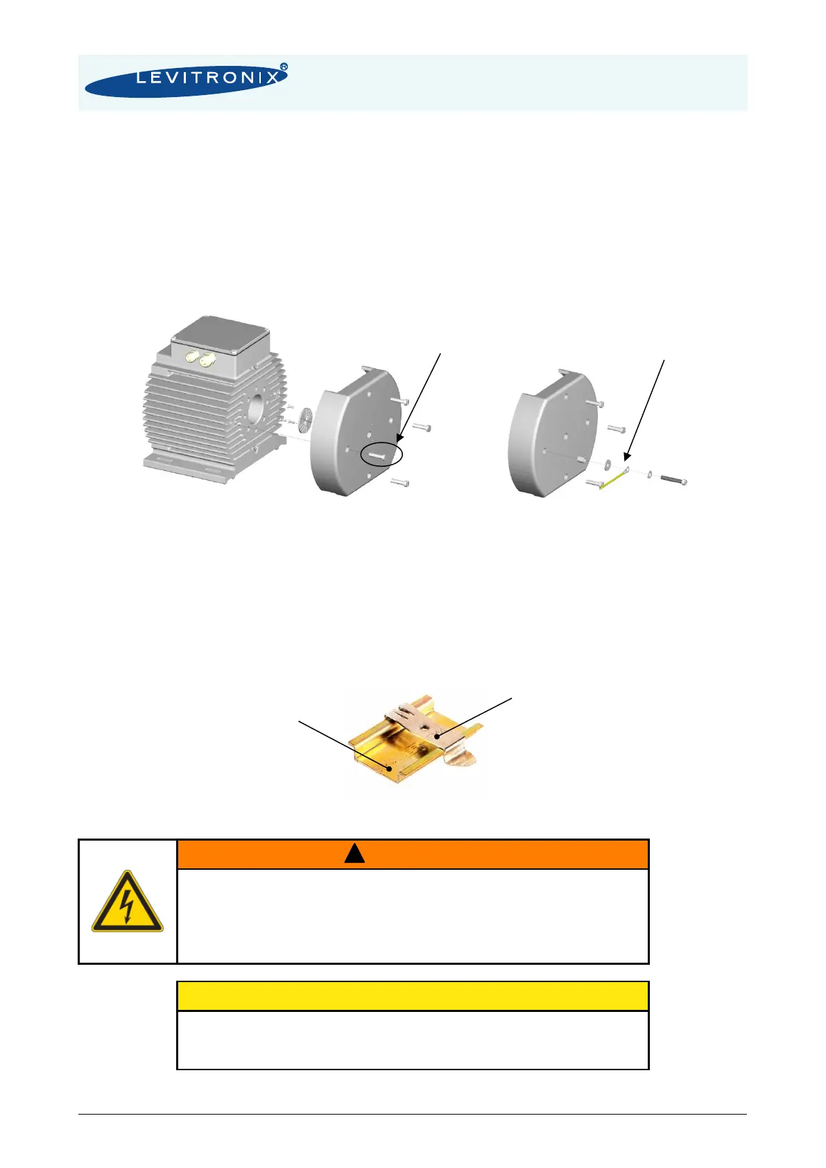
2) Motors used with cooling module ACM-4.3
A protective earth wire shall be attached to the ATEX / IECEx specific motor housing by using one of the
four M6 threads on the backside of the motor.
▪ Mount the cooling module ACM-4.3 to the motor according to Figure 10
▪ Remove one of the four M6 screws on the mounted cooling module
▪ Use a crimp cable lug to connect the earth wire
▪ Attach the crimp cable lug with a M6x40mm stainless steel screw, a washer disc and a spring
lock washer to the motor through the cooling module (see Figure 31)
Figure 31: Attachment of a protective earth wire to the backside of the motor through ACM-4.3
4.3 Mechanical Installation of the Controller
▪ The controller can be mounted with the 2 DIN rail brackets on the housing (see Figure 11)
▪ If no forced air-cooling is used, mount the controller in upright position and assure that the
heat of the controller can dissipate. Avoid mounting the controller in a cabinet where heat is
stagnated and accumulated.
Figure 32: Din-rail bracket for mounting of the LPC-2000 controller
Hazardous voltage may be present.
In order to avoiding fluid spills shorting mains or other voltages within the
controller, place the controller in a spill protected electronic cabinet. If
explosive flammable gases are present, place the controller in an
explosion-proof cabinet.
Do not under any circumstances open the controller. Levitronix
®
does not
assume responsibility for any damage, which occurs under such
circumstances.