16
Min 85 mm
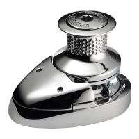
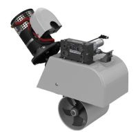
Standard Motor/gearbox Fig 5.6
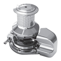
Hi-Power Motor/gearbox Fig 5.5
GB
5.5 Model V8 motor ports & drain - Hi-Power motor/gearbox
The Lewmar hydraulic motor ports are:
A & B ports ¾” BSP.
Drain port (only Hi-Power motor/gearbox) is ¼” BSP.
• The location of the ports for the Hi-Power motor/gearbox is shown in Fig 5.5. A drain line is required for the
motor/gearbox.
• The minimum bore diameter of the drain line required is 6mm.
Safe working pressure: 10 bar.
• Tubing material: Oil compatible semi-rigid plastic tube braided hose or steel pipe.
5.6 Model V8 Motor ports - Standard motor/gearbox
The location of the ports for the Standard motor/gearbox is shown in Fig 5.6 (no drain connection).
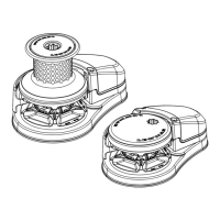
5.7 Model V9/10/12 motor ports & drain
The Lewmar hydraulic motor ports are:
A & B ports ½” BSP.
Drain port is ¼”BSP.
1. Hydraulic installation schematic:
• V9 - 5:1 Hydraulic gearbox (with brake) 300cc motor.
• V9 - 7:1 Hydraulic gearbox 230cc motor.
• V10 - 5:1 Hydraulic gearbox (with brake) 500cc motor.
• V12 - 13:1 Hydraulic gearbox (with brake) 250cc motor.
2. The location of the ports for the motor/gearbox is shown in Fig 5.7-2.
• A drain line is required on V9/10/12 motor/gearbox with brake.
• The minimum bore diameter of the drain line required is 10mm (⅜”).
Safe working pressure: 10 bar.
• Tubing material: Oil compatible semi-rigid plastic tube braided hose or steel pipe.