Lexicon
4-17
4. Move the cable from the Left Main Output jack to the Right Main Output Jack.
5. Verify its output level reading is between 27.06 to 24.94 dBu (17.5 to 13.7 Vrms).
Signal Level with 600Ω Load:
1. Apply a 1kHz-sinewave signal with a 600Ω load at -11dBu (218 mVRMS).
2. Verify an output level reading between 17.86 to 15.74 dBu (6 to 4.7 Vrms).
3. Move the cable from the Right Insert Return jack to the Left Insert Return jack.
4. Move the cable from the Right Main Output Jack to the Left Main Output Jack.
5. Verify its output level reading is between 17.86 to 15.74 dBu (6 to 4.7 Vrms).
6. Remove the 600Ω load.
Frequency Response Measurement:
1. Disable all Filters on the Distortion Analyzer.
2. Apply a 1kHz-sinewave signal at -11dBu (218 mVRMS).
3. Set the Analyzer for a 0dB reference.
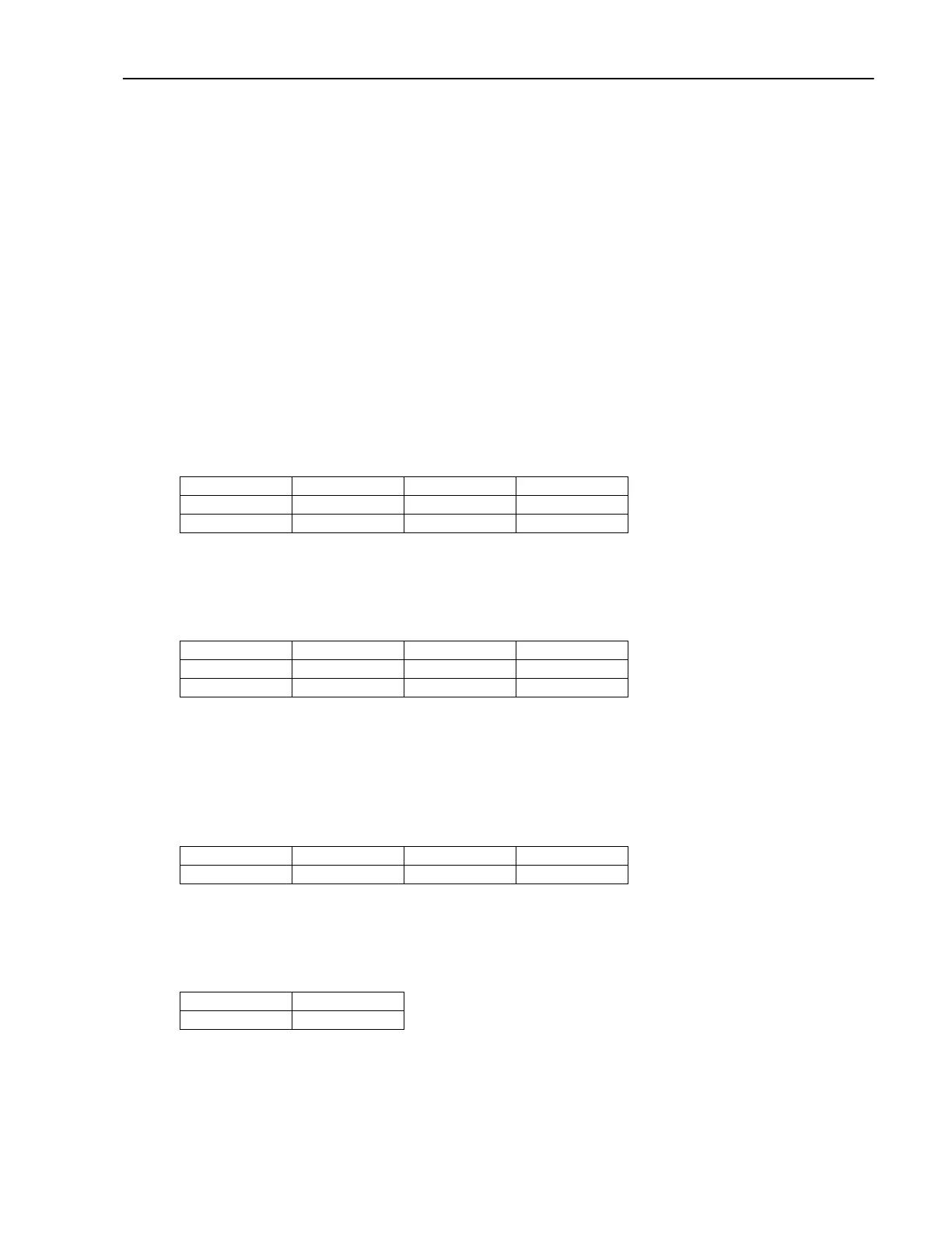
4. Verify the output level reading is between 1.06 to -1.56 dBu (875 to 647 mVRMS) at the following
frequency settings.
20,000Hz 16,000Hz 12,000Hz 10,000Hz
4,000Hz 2,000Hz 250Hz 100Hz
60Hz 20Hz
5. Move the cable from the Left Insert Return jack to the Right Insert Return jack.
6. Move the cable from the Left Main Output jack to the Right Main Output Jack.
7. Verify the output level reading is between 1.06 to -1.56 dBu (875 to 647 mVRMS) at the following
frequency settings.
20,000Hz 16,000Hz 12,000Hz 10,000Hz
4,000Hz 2,000Hz 250Hz 100Hz
60Hz 20Hz
8. Enable the Lo pass filters on the analyzer (30kHz or 20kHz).
Crosstalk Left/Right Measurements:
1. Move the cable from the Right Main Output Jack to the Left Main Output Jack.
2. Verify the crosstalk output level reading is between -62.94 to -120 dBu (552 to 1.2 uVRMS) at the
following frequency settings.
20,000Hz 15,000Hz 10,000Hz 5,000Hz
3,000Hz 997Hz 100Hz 20Hz
3. Move the cable from the Right Insert Return jack to the Left Insert Return jack.
4. Move the cable from the Left Main Output jack to the Right Main Output Jack.
5. Verify the crosstalk output level reading is between -62.94 to -120 dBu (552 to 1.2 uVRMS) at the
following frequency settings.
20,000Hz 10,000Hz
997Hz 100Hz
THD+N Measurement:
1. Connect an audio input cable between the Low Distortion Oscillator and the MPX G2 Left Insert Return
jack.
2. Connect an audio output cable from the Left Main ¼” Output jack on the rear of the MPX G2 to the
Distortion Analyzer.