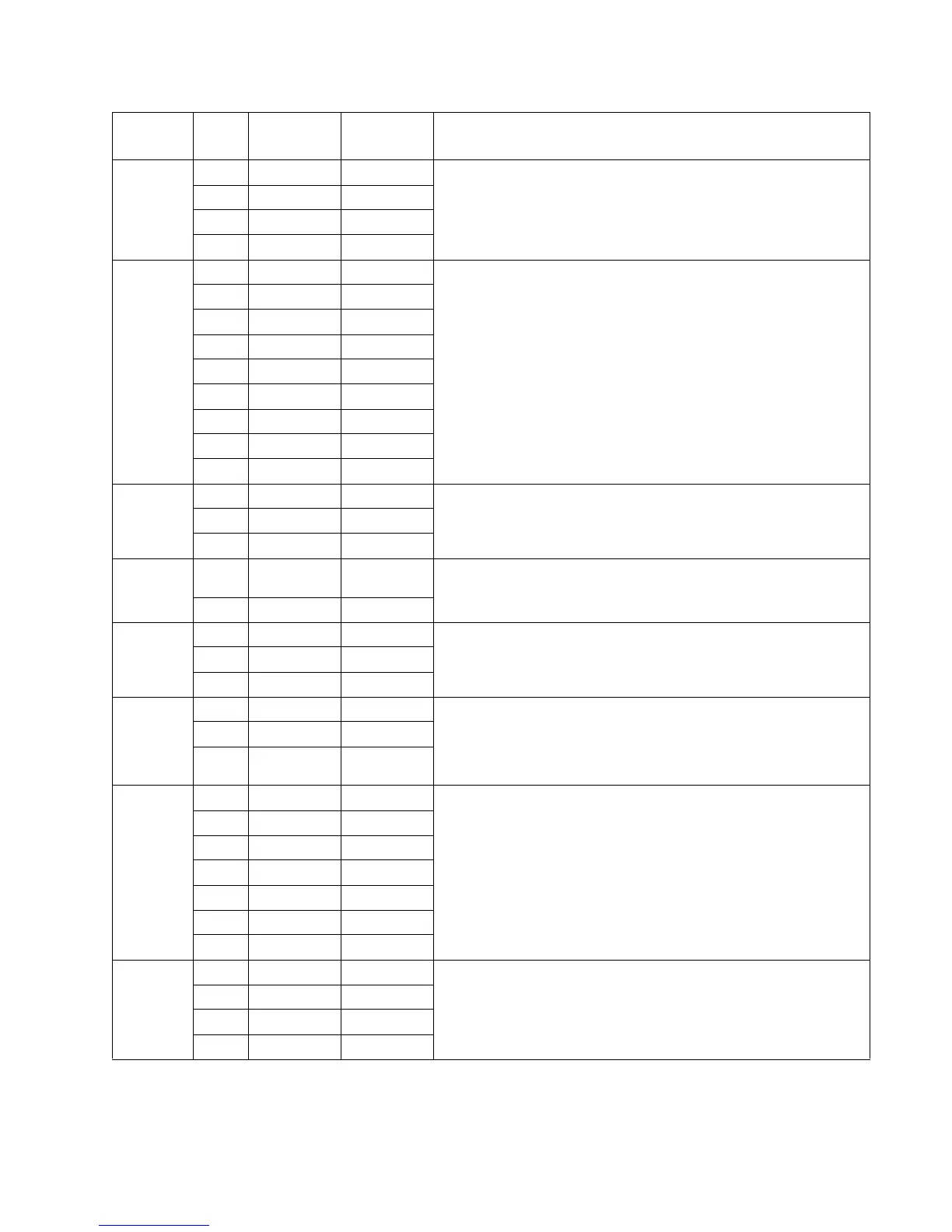
Locations and connections 5-3
4512-420, -430
J13 1 Mirror motor, Ready mode
2, 3 +5 V dc +5 V dc
4 Ground Ground
5 +24 V dc +24 V dc
J14 1 – LSU, Ready mode
2 Ground Ground
3 +3.3 V dc –
4 Signal –
5 +3.3 V dc –
6 Ground Ground
7+5Vdc+5Vdc
8 Ground Ground
9+5Vdc–
J15 1 +5 V dc 0 V dc Door open sensor, Ready mode (door closed)
2+5Vdc+5Vdc
3 Ground Ground
J16 1 Approx.
+2 V dc
Approx.
+5 V dc
Thermistor
2 Ground Ground
J17 1 +1.1 V dc +5 V dc Exit sensor, Ready mode
2+5Vdc+5Vdc
3 Ground Ground
J18 1 Ground Ground Fan, Ready mode (fan running)
2 +11–12 V dc +24 V dc
3Approx.
+1.5 V dc
+3.2 V dc
J19 1 Ground Ground Operator panel, Ready mode. LED and LCD panels use the same
common connector.
2+5Vdc+5Vdc
3 0Vdc 0Vdc
4+5Vdc+5Vdc
5+5Vdc+5Vdc
6LED ONLY+5Vdc
7+5Vdc+5Vdc
J20 1 +1.1 V dc +5 V dc Manual feed sensor
2+5Vdc+5Vdc
3 Ground Ground
4– –
Connector Pin #
Value
(plugged)
Value
(unplugged) Comments