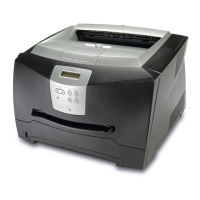
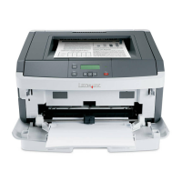
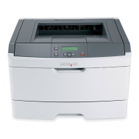
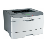
5-2 Lexmark™ E350d, E352dn
4512-420, -430
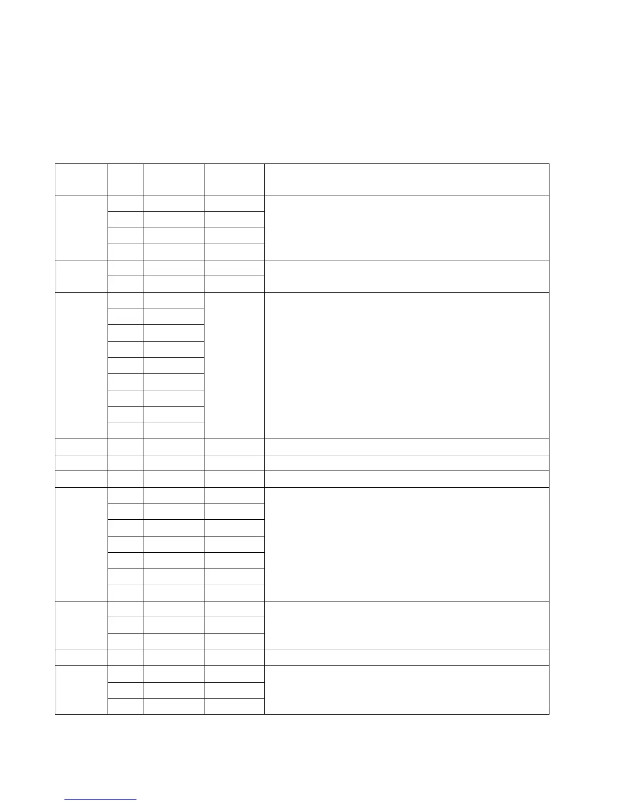
Controller card connector pin values
Note: See the wiring diagram at back of book.
These values were measured with all connections made (plugged) or with only one connector at a time
unplugged to expose the pins. Always disconnect and connect with the printer power off. Otherwise, the values
below may not match.
Connector Pin #
Value
(plugged)
Value
(unplugged) Comments
J2 1, 4 +5 V dc +5 V dc Without tray 2 attached; Ready mode
2 +24 V dc +24 V dc
6 Ground Ground
3, 5 Signal Signal
J3 1, 3 +24 V dc +24 V dc Manual and paper feed solenoids; Ready mode
2, 4 +24 V dc 0 V dc
J4 1, 2 0 V dc Main power
source to
controller
card
LVPS/HVPS; Ready mode
3. 4 +5 V dc
5, 6 Signal
7 Ground
8, 9 +24 V dc
10 Signal
11 +5
12, 14 Ground
13 Signal
J5–––USB port
J6 – – – Network port (Ethernet)
J7 – – – Parallel port
J8 1 – +3.3 V dc Ready mode, main motor drive.
2– +3.3Vdc
3– +3.3Vdc
4– +3.3Vdc
5 Ground Ground
6+5Vdc+5Vdc
7, 8, 9 +24 V dc <+24 V dc
J9 1 +1.1 V dc +5 V dc Input sensor, Ready mode
2+5Vdc+5Vdc
3 Ground Ground
J10 1, 2 Signal Signal Smart chip
J11 1 Signal Signal Toner low sensor
2 Ground Ground
3 Signal Signal