S-Device Supervisor Object
17200138_002_C0 – (2016-10) –
Leybold
13
Each of the three structure members is defined as a structure containing an or-
dered list (i.e., array) of bytes of length SIZE, and an unsigned integer whose value
is SIZE. Each of the bytes in each array has a specific mapping. This mapping is
formatted as 8 bits representing 8 independent conditions, whereas a value of 1
indicates that the condition is set (or present), and a value of 0 indicates that the
condition is cleared (or not present). Note that if a device does not support an
exception detail, the corresponding bit is never set. The bitmaps for alarms and
warnings in the corresponding attributes are structured in parallel so that a condi-
tion may have either alarm or warning set depending on severity. If a condition
inherently cannot be both alarm and warning, then the parallel bit position corre-
sponding to the other state will remain "0".
This structure relates exception conditions (i.e., alarms or warnings) which are
common to all devices within the Hierarchy of Semiconductor Equipment Devices.
The Detail element of the structure is an ordered list (i.e., array) of bytes of length
[SIZE=2] which is the value of the structure element size.
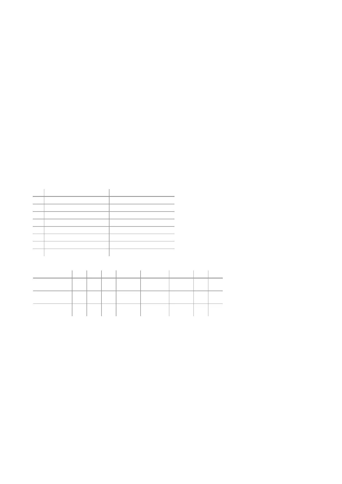
Two bytes Common Exception Detail are provided: Common Exception Detail[0]
and Common Exception Detail[1]. The specific exception associated with each of
the bitmaps is given in the table below. The SIZE for this revision is two (2).
Bit Common Exception Detail [0] Common Exception Detail [1]
0 0 0
1 0 0
2 EPROM exception 0
3 EEPROM exception power supply input voltage
4 RAM exception 0
5 reserved 0
6 0 0
7 0 0
Data Component Bit 7 Bit 6 Bit 5 Bit 4 Bit 3 Bit 2 Bit 1 Bit 0
Common Excep-
tion Detail Size
0 0 0 0 0 0 1 0
Common Excep-
tion Detail 0
0 0 0
Data
Memory
Nonvolatile
Memory
Code
Memory
0 0
Common Excep-
tion Detail 1
0 0 0 0
PS Input
Voltage
0 0 0
This structure, similar in form to Common Exception Detail, relates exception con-
ditions which are specific to individual devices on the network and are defined in
the following. The Detail element of the structure is an ordered list (i.e. array) of
bytes of length [SIZE = 4 for alarms and SIZE = 5 for warning] which is the value of
the structure element size.
This structure, similar in form to Common Exception Detail, relates exception con-
ditions which are specific to the manufacturers of individual devices on the network.
There is one byte manufacturer exception details defined. The Detail element of
the structure is an ordered list (i.e., array) of bytes of length [SIZE = 1] which is the
value of the structure element size.
Manufacturer Exception Detail
Device Exception Detail
Common Exception Detail
Common Exception Detail
Attribute Values
Common Exception Detail Format
Summary