IONIVAC
ITR 90
ITR 90 P
Instruction Sheet KA09420 _ 002 _
CO
Incl.
EU
Declaration
of
Conformity
Part Numbers
120 90
120
91
120 92
120 94
230 030
230
031
Product
Identification
In
all communications with Leybold, please specify the
information given
on
the product nameplate. For convenient
reference transfer this information into the diagram below.
Leybold GmbH, 0-50968
KOln
Type:
No:
F-No:
!(E~I
v w
Validity
This document applies to products with the following part
numbers:
ITR
90
Without display:
120
90
(DN
25
ISO-KF)
120
92
(DN
40
CF-R)
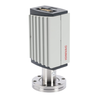
ITR
90
With display
120
91
(DN
25
ISO-KF)
120 94
(DN
40
CF-R)
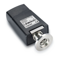
\TR
90
P (with Profibus intertace and switching functions)
230 030
(ON
25
/SO-KF)
230
031
(ON
40
CF-R)
The part number (No) can be taken from the product name
plate.
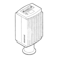
If not indicated otherwise
in
the legends, the illustrations
in
this document correspond to the gauge with part number
120 90. They apply to the other gauges by analogy.
We
reserve the right to make technical changes without prior
notice.
All dimensions
in
mm.
Intended
use
The gauges ITR 90 and ITR 90 P have been designed for
vacuum measurement gases and gas mixtures
in
a pressure
range 5x 10·
10
...
1000 mbar.
They must not be used for measuring flammable or
combustible gases
in
mixtures containing oxidants (e.g.
atmospheric oxygen) within the explosion range.
The gauges can be operated
in
connection with the
COMB IV
AC®
IT23 or with another evaluation unit.
Functional
Principle
Over the whole measurement range, the Hot Ion Cambi
Gauges have a continuous characteristic curve and its
measuring signal is output as logarithm
of
the pressure.
The gauge functions with a Bayard Alpert hot cathode
ionization measurement system (for p <
2.0x10·
2
mbar) and a
Pirani measurement system (for p >
5.5x
10-
3
mbar).
In
the
overlapping pressure range of
2.0x10-
2
...
5.5x10·
3
mbar a
mixed signal
of
the two measurement systems
is
output. The
hot cathode is switched
on
by the Pirani measurement
system only below the switching threshold of
2.4x10·
2
mbar
(to prevent filament burn-out). It
is
switched off when the
pressure exceeds 3.2x
10-
2
mbar.
Trademark
COMBIVAC® Leybold G,bH
Caution
Information on correct handling or use. Disregard can
to malfunctions or minor equipment damage.
Personnel
Qualifications
All work described
in
this document may only be carried
out by persons who have suitable technical training and
the necessary experience or who have been instructed by
end-user of the product.
General Safety
Instructions
• Adhere to the applicable regulations and take the ne-
cessary precautions for the process media used.
Consider possible reactions with the product materials.
Consider possible reactions (e.g. explosion) of the
process media due to the heat generated by the product.
• Adhere to the applicable regulations and take the ne-
cessary precautions for all work you are going to do and
consider the safety instructions
in
this document.
• Before beginning to work, find out whether any vacuum
components are contaminated. Adhere to the relevant
regulations and take the necessary precautions when
handling contaminated parts.
Communicate the safety instructions to all other users.
Liability
and
Warranty
Leybold assumes no liability and the warranty becomes null
and void if the end-user or third parties
• disregard the information
in
this document
• use the product
in
a non-conforming manner
• make any kind
of
changes (modifications, alterations etc.)
to the product
• use the product with accessories not listed
in
the product
documentation.
The end-user assumes the responsibility
in
conjunction with
the process media used.
Transmitter failures due to contamination or wear and tear as
well as expendable parts (e.g. filaments) are not covered by
the warranty.
nical
Data
In
some points, the technical data of ITR 90 P differ
from those of ITR
90,
which are given below
(-+ "Technical Data"
in
m [1] and [2]).
Display range
(air,
0
2
,
CO, N
2
)
Measurement range
(air, 0
2
,
CO, N
2
)
Accuracy
Repeatability
Emission
Switching on threshold
Switching off threshold
Emission current
p
:5
7.2x10-
6
mbar
7.2x10-
6
mbar < p <
3.2x10·
2
mbar
Degas
5x10·
10
...
1000 mbar
continuous
1x10-
8
...
10-
2
mbar
continuous
15%
of
reading
( after 5 min. stabilization)
5% of reading
after 5 min.
stabilizationL_
2.4x10·
2
mbar
3.2x10-
2
mbar
5 mA
25
µA
7.2x10·
6
mbar
Current
(p
<
7.2x10_,,
mbar) =16 mA I =4.0 W
Control input signal
O V / 24
V,
PLC level,
high active
Duration <3 min, followed by
automatic stop
In
degas mode, the ITR
90
keeps supplying measurement
values the tolerances of which can be higher than during
normal operation.
---------------
Output signal
(measuring signal)
Display range
0 ...
10V
0.774V
...
10V
(5x 10·
10
mbar ... 1000 mbar)
Relationship voltage-pressure logarithmic,
Error signal
Minimum loaded impedance
Gauge identification
0.
75
VI
decade
<0.3
VI
0.5 V
10
kQ
--··-··-----··-··-····------
42
kQ
between Pin 1 0 and
-----·----------
_ .
___
Pin 5 (9!Jlll,e cable)_
__
.
RS232C interface
Baud rate
Data format
Signal level
Connector
9600 baud
binary data set
8 data bits
one stop-bit
no parity-bit
no handshake
=±8
V
---?
Power connection
. Further information
on
the
_RS232C
interface -+ m
J11
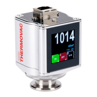
Display
Panel
Dimensions
Measurement units
LCD matrix,
32x16 pixels,
with background illumination
16.0 mm x 11.2 mm
mbar (default),
Torr,
Pa
Ch~g
the measurement
unit-+
mJ:cl
_____
_
Supply
The gauge may only be connected to supply and
evaluation units that conform to the
requirements
of
a grounded protective extra-low
voltage (PELV). The connection to the gauge
has to be fused
11
.
Voltage at gauge
Power consumption
Standard
Degas
Emissions start (200 ms)
Power consumption
~use
nece~~a_ry~---··--·-
24 voe (20 ...
28
VDC)
(:5ripple 2
Vpp)
21
:50.5A
:50.8
A
:51.4
A
:516W
S:1.25
AT
11
Leybold
controllers fulfill these requirements.
2
)
The minimum voltage
of
the power supply must be increased
proportionally
to
the
length
of
the measuring cable.