Electrical connection
Sensor cable
For analog values only
without degas-function
For analog values
with degas-function
All functions
incl. RS232C interface
Cable length (24 VDC)
For operation with RS232C
interface
Materials
on
the vacuum
side
Housing, supports,
screens
Feedthrough
Isolator
Cathode
Cathode holder
Connection, D-Sub, 15-pin
4-pin plus screening
5-pin plus screening
7-pin plus screening
:535
m (4/5/?x0.25 mm
2
)
:550
m (4/5/7x0.34
mm')
:5100
m (4/5/7x1
.0
mm')
:530m
stainless steel
NiFe nickel plated
glass
lr,Y
2
0
3
Mo
Pirani element W, Cu
Internal volume
120 90, 120
91,
230030 z24
cm
3
____
12092,_12094,
230031
z34cm
3
__________________
_
Admissible temperatures
Storage
Operation
Bake out
Relative humidity
Year's mean
During 60 days
Use
.-1:.l'Qe
of 1:irotection
Dimensions
4-40UNC
28
Weight
120
90
120
91
230
030
-20
... +70
°C
0
..
+50
°C
150
°C
(without electronics unit)
:565%
(no condensation)
585% (no condensation)
indoors only atitude
up
to
2000 m
IP30,
____
_
4-40UNC
28
12090,
12091
285g
12092,
12094
550g
230 030 430 g
---
230
031
________
695 g
--------
---------
_
Measuring
signal
vs. pressure
Pressure p [mbar)
4.0
5,0 6.0 7.0
Measuring signal U[V]
[VJ
[VJ
[VJ
p = i Q(U-7.75)/0.75+c
[mbar]
[Pa]
[Torr]
0
2
-0.125
where
p
u
c
pressure
measuring signal
constant (pressure unit dependent)
Gas
type
dependence
For gases other than air, the pressure
in
the indication range
p
<
10·
3
mbar can
be
determined by a simple conversion:
Pett=
K x pressure indicated
Gas type Calibration Gas ] Calibration
_
~y_pe
--f--
factor C
He
i 5.9
Ne
i
4.1
Kr , 0.5
Ar 0.8
air,
0
2
,
CO,
N
2
H,
Xe
1.0
2.4
0.4
~t,
!:Vacuum
Connection
DANGER: overpressure
in
the vacuum system
>1
bar
Injury caused by released parts and harm
caused by escaping process gases can result if
clamps are opened while the vacuum system is
pressurized.
Do
not open any clamps while the vacuum sys-
tem
is
pressurized. Use the type clamps which
are suited to overpressure.
DANGER: protective ground
Incorrectly grounded products can
be
extremely
hazardous
in
the event of a fault.
The gauge must
be
electrically connected
to
the
grounded vacuum chamber. This connection
must conform to the requirements
of
a protective
connection according to
EN
61010:
• CF connection fulfill this requirement
• For gauges with a
KF
flange, use a conduc-
tive metallic clamping ring
Caution
Caution: vacuum component
Dirt and damages impair the function
of
the vac-
uum component.
When handling vacuum components, take ap-
propriate measures to ensure cleanliness and
prevent damages.
&
Caution
Caution: dirt sensitive area
Touching the product or parts thereof with one's
bare hands increases the desorption rate.
Always wear clean, lint-free gloves and use cle-
an
tools when working
in
this area.
ll3J=
The gauge may
be
mounted
in
any orientation. To
keep condensates and particles from getting into the
measuring chamber preferably choose a horizontal
to
upright position and possibly use a seal with a
centering ring and filter.
The gauge is supplied with a built
in
grid. For potentially con-
taminating applications and to protect the electrodes against
light and fast particles, installation of the optional baffle is
recommended(---) m [1]).
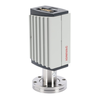
Remove the protective
lid
and install the product at the
vacuum system.
Seal with centering ring
Keep the lid.
Seal with centering
ring and filter
Power
connection
II:]f'
The following information
on
the electrical con-
nection
as
well
as
the wiring diagram applies
to
ITR 90 only(---) W [1] and [2] for details
on
the
electrical connection and additional functions
of
ITR
90
P).
IIff
Make sure the vacuum connection is properly made
(---)
"Vacuum Connection").
0 If
no
connection cable
is
available, make one according
to the following diagram.
ITR90
-·
I _____ _
TxD
RxD
Measuring
sign
a!
~4Di;
i-1
i v +
12
. I -
Degas
7
)1--i'-':-----
! i
8):j
5
..
10
~Identification
15
L------·-
-
------------·J
Electrical connection
Pin
2 Signal output (measuring signal)
Pin
5 Supply common, GND
Pin 7 Degas
on,
active high
Pin
8 Supply
Pin
10 Gauge identification
Pin
12 Signal common, GND
Pin
13 RS232C, TxD
Pin
14 RS232C, RxD
Pin
15 Shielding, housing, GND
Pins
1,
3,
4,
6,
9 and
11
are
not connected internally.
0 ...
+10V
+24 voe
+24 voe
gfl
1
15-M
8
D-Sub,
15
pins
female,
soldering side
11111111111111111111111111111111111111111111111111111111111111111111111111111111
kao9420.002.c0
(2016-10)
Original: German KA09420_001_CO (2016-10)
 Loading...