C8b
CONTINUED
until
the
long pin (65) forces
the
other
short
pin (the
one
that
aligns
the
front
end
plate (44) and
the
second
stage
pump
cylinder)
to
fall
out,
and
then
the
long pin also falls
out
of
the
front-end-
plate
alignment
hole (see Figure 5-5).
c.
Repeat
Steps
C-8a
and
C-8b
for
the
two
short
and
one
long cylindrical pins
on
the
other
side
of
the
module.
55
1TA-4.20
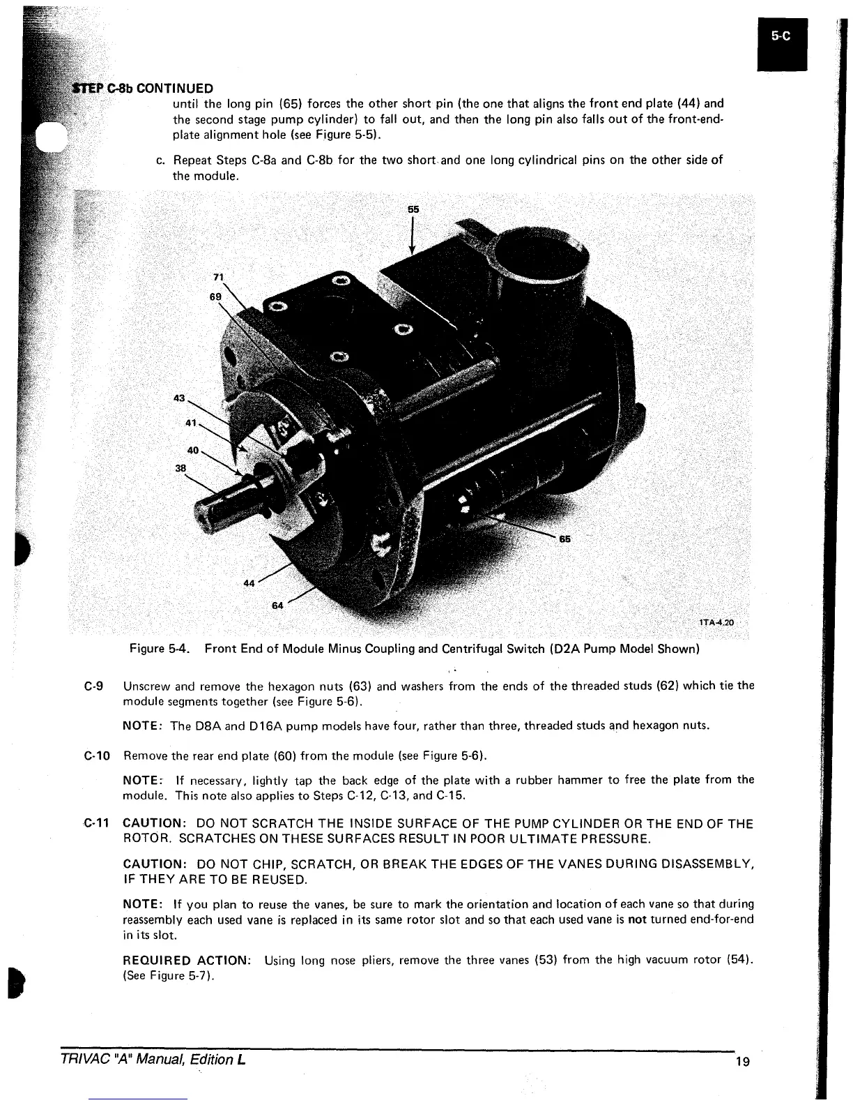
Figure 5-4.
Front
End
of
Module Minus Coupling and Centrifugal
Switch
(D2A
Pump
Model
Shown)
C-9 Unscrew
and
remove
the
hexagon
nuts
(63) and washers from
the
ends
of
the
threaded
studs
(62) which tie
the
module
segments
together
(see Figure 5-6).
NOTE:
The
D8A
and
0
16A
pump
models
have four,
rather
than
three,
threaded
studs
and
hexagon nuts.
C-10 Remove
the
rear
end
plate
(60)
from
the
module
(see Figure 5-6).
NOTE:
If
necessary, lightly
tap
the
back edge
of
the
plate
with
a
rubber
hammer
to
free
the
plate from
the
module. This
note
also applies
to
Steps
C-12, C-13, and C-15.
C-11 CAUTION:
DO
NOT
SCRATCH
THE
INSIDE
SURFACE
OF
THE PUMP CYLINDER OR THE END OF THE
ROTOR.
SCRATCHES
ON
THESE
SURFACES
RESULT
IN
POOR ULTIMATE PRESSURE.
CAUTION: DO
NOT
CHIP, SCRATCH, OR BREAK THE EDGES
OF
THE
VANES DURING DISASSEMBLY,
IF
THEY
ARE
TO
BE
REUSED.
NOTE:
If
you
plan
to
reuse
the
vanes, be sure
to
mark
the
orientation
and
location
of
each vane so
that
during
reassembly each used vane
is
replaced in its same
rotor
slot
and so
that
each used vane
is
not
turned
end-for-end
in
its slot.
REQUIRED
ACTION: Using long nose pliers, remove
the
three
vanes (53)
from
the
high vacuum
rotor
(54).
(See Figure 5-7).
TRIVAC
"A"
Manual, Edition L
19
 Loading...


