/'
Step F-6 e (Cont'd.)
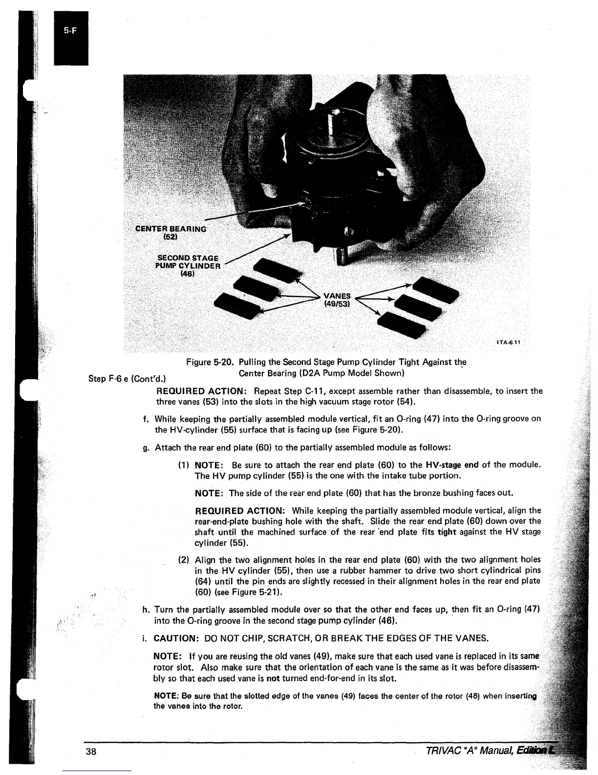
Figure 5-20. Pulling
the
Second Stage Pump Cylinder Tight Against
th,e
Center Bearing (D2A Pump Model Shown)
38
REQUIRED ACTION: Repeat Step C-11,
except
assemble rather than disassemble,
to
insert the
three vanes (53) into the slots
in
the
high vacuum stage
rotor
(54).
f. While keeping
the
partially assembled module vertical, fit an a-ring (47) into
the
a-ring groove on
the HV-cylinder (55) surface
that
is
facing
up
(see Figure 5-20).
g.
Attach
the
rear end plate (60)
to
the
partially assembled module
as
follows:
(1) NOTE:
Be
sure
to
attach the rear end plate (60)
to
the
HV-stage end
of
the module.
The
HV
pump
cylinder (55)
is
the
one with the intake
tube
portion.
NOTE: The side
of
the
rear end plate (60)
that
has the bronze bushing faces
out.
REQUIRED ACTION: While keeping
the
partial1y assembled module vertical, align the
rear-end-plate bushing hole with
the
shaft. Slide the rear end plate (60) down over
the
shaft until
the
machined surface
of
the rear 'end plate fits tight against the
HV
stage
cylinder (55).
(2) Align
the
two
alignment holes
in
the
rear end plate (60) with
the
two
alignment holes
in
the
HV
cylinder (55), then use a rubber hammer
to
drive
two
short
cylindrical pins
(64) until
the
pin ends are slightly recessed
in
their alignment holes
in
the rear end plate
(60) (see Figure 5-21).
h. Turn
the
partially assembled module over so
that
the
other
end faces up, then fit an a-ring (47)
into
the
O-ring groove
in
the second stage
pump
cylinder (46). '
i.
CAUTION:
DO
NOT CHIP, SCRATCH, OR BREAK THE EDGES OF THE VANES.
NOTE:
If
you are reusing
the
old vanes (49), make sure
that
each used vane
is
replaced
in
its same
rotor slot. Also make sure
that
the orientation
of
each vane
is
the
same
as
it was before disassem-
bly so
that
each used vane
is
not
turned end-for-end
in
its slot.
NOTE: Be sure that the slotted edge of the vanes (49) faces the center
of
the rotor
(48)
when inserting
the vanes into the rotor.
TRIVAC
"A"
Manual,
 Loading...


